Connecting joint construction

A technology for connecting joints and structures, applied in sleeve/socket connections, pipes/pipe joints/fittings, passing components, etc., can solve problems such as lock nut looseness, achieve loosening prevention, reliable connection, and improve workability Effect

Inactive Publication Date: 2013-03-06
BRIDGESTONE CORP
View PDF6 Cites 2 Cited by
  • Summary
  • Abstract
  • Description
  • Claims
  • Application Information

AI Technical Summary

Problems solved by technology

[0003] However, in the joint structure of the above-mentioned patent documents, for example, in the case of hydraulic pipes used in construction machinery, such as heavy machines, there is a screw-in type lock nut ( retaining ring) the possibility of loose
In addition, if the fixing ring is loose, if the spring-shaped fixing fitting (clamp) is damaged or disengaged due to external factors such as some kind of impact, there is a possibility that the connection between the hydraulic pipes will be disconnected and oil will leak out.

Method used


Image

  • Connecting joint construction
  • Connecting joint construction
  • Connecting joint construction

Examples


no. 1 Embodiment approach

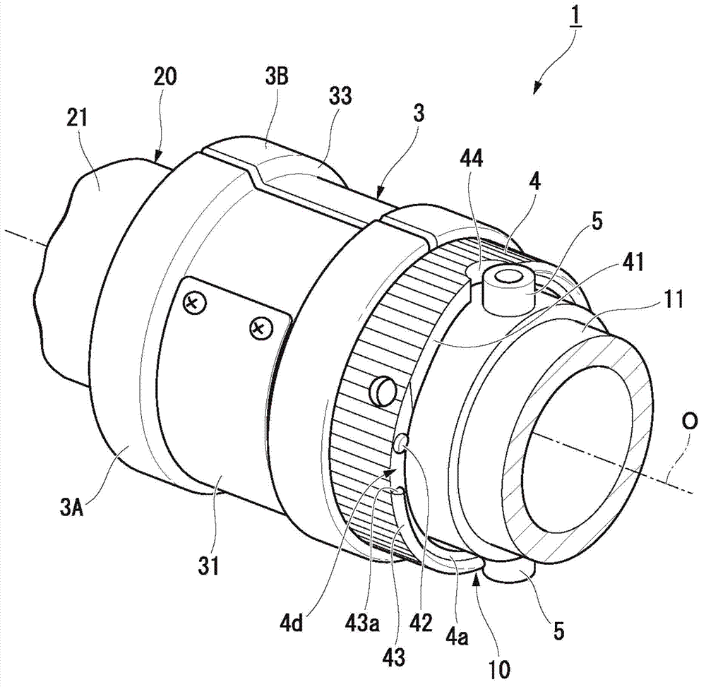
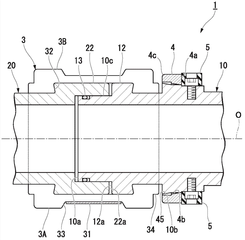
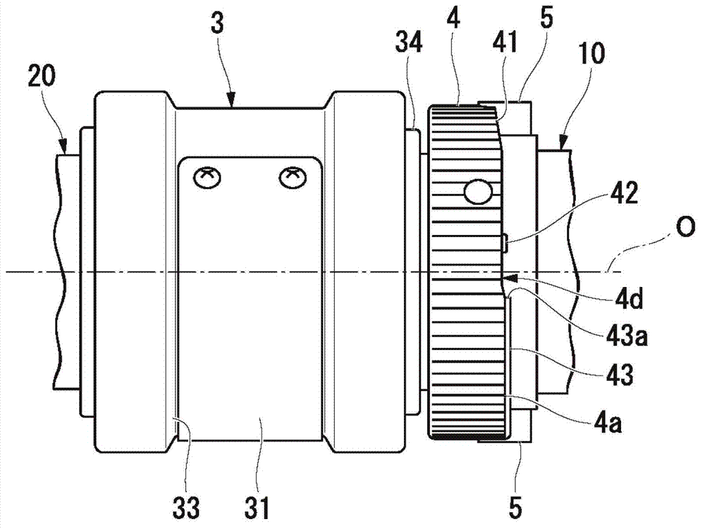
[0045] Such as figure 1 and figure 2 As shown, the connecting joint structure 1 of this embodiment is a structure for firmly connecting the male joint 10 (first joint) and the female joint 20, and the male joint 10 (first joint) is overlaid on the first hydraulic pipe 11 ( pipe body), the female joint 20 is overlaid on the end of the second oil pressure pipe 21 (pipe body).

[0046] In addition, the above-mentioned male joint 10 (first hydraulic pipe 11 ) and female joint 20 (second hydraulic pipe 21 ) are arranged such that their respective central axes are located on a common axis. In the present embodiment, the common axis is referred to as the piping axis O, the direction perpendicular to the piping axis O is referred to as the radial direction, and the direction around the piping axis O is referred to as the circumferential direction. In the male joint 10 and the female joint 20 , the connection side along the pipe axis O direction is referred to as the distal end side, ...

no. 2 Embodiment approach

[0074] Such as Figure 8 shown, replace figure 2 The structure of the above-mentioned first embodiment for connecting the male joint 10 and the female joint 20 is shown, and the connecting joint structure 1A of the second embodiment is suitable for connecting the nozzles and nozzles on the coaxial line by using the intermediate joint 6 (second joint). The structure between male joints 10A, 10B (first joints) connected by 14A, 14B.

[0075] The male joints 10A and 10B have the same structure as the male joint 10 in the first embodiment described above, and detailed description thereof will be omitted here.

[0076] The intermediate joint 6 includes: a main body 61 at the center in the direction of the pipe axis O; and female-side locking rings 62 provided on both sides of the main body 61 and capable of being inserted and fitted in the male joints 10A, 10B. In the outer peripheral edge portion 10c. Here, the male connector of reference numeral 10A (in Figure 8 The connect...


PUM


Abstract

The invention provides a connecting joint construction (1), comprising a clamp (3) which clamps a first joint (10) and a second joint (20) to make the first and second joints (10, 20) be embedded in a communication manner; a fixing ring (4) arranged on the first joint (10), arranged in a manner of free sliding in a tubing axial direction, and is pushed towards the side of the clamp (3) in the tubing axial direction to press the clamp (3); and a convex component (5) protruded from the peripheral surface of the first joint (10) wherein the fixing ring is arranged. Moreover, any one of the fixing ring (4) and the convex component (5) can be distorted elastically, and in the state that any one of the fixing ring (4) and the convex component (5) is elastically distorted, the fixing ring is clamped between the convex component (5) and the clamp (3), and presses the clamp (3), so that the first and second joints (10, 20) are connected.

Description

technical field [0001] The present invention relates to a connecting joint structure for connecting joints provided on a pipe body. Background technique [0002] Conventionally, transition joints are known as joints for connecting high-pressure pipes and the like. As a transition joint, for example, DE19642338C discloses a hydraulic pipe joint structure in which a spring-shaped fixing fitting is used to clamp the connecting portion of the male and female joint members to fix the male, female, and male members. This connection part of the female joint member. In this joint configuration, the spring-like fixing fittings for fixing between the joints are tightened by a lock nut, thereby preventing the fixing fittings from coming off. [0003] However, in the joint structure of the above-mentioned patent documents, for example, in the case of hydraulic pipes used in construction machinery, such as heavy machines, there is a screw-in type lock nut ( retaining ring) the possibi...

Claims


Application Information

Patent Timeline
Patent Type & Authority Applications(China)
IPC IPC(8): F16L21/06
Inventor 伝田刚
Owner BRIDGESTONE CORP
Why Eureka
Try Eureka