Magnetic position sensors, systems and methods

A magnetic sensor, sensor technology, applied in the field of sensors, can solve complex mathematical calculations, inaccurate solutions, difficult calculations and other problems

Active Publication Date: 2013-03-06
INFINEON TECH AG
View PDF6 Cites 28 Cited by
  • Summary
  • Abstract
  • Description
  • Claims
  • Application Information

AI Technical Summary

Problems solved by technology

Other solutions are inaccurate and / or require complex mathematical calculations that are difficult to perform with limited silicon area

Method used


Image

  • Magnetic position sensors, systems and methods
  • Magnetic position sensors, systems and methods
  • Magnetic position sensors, systems and methods

Examples


Embodiment Construction

[0027] Embodiments relate to magnetic position sensors.

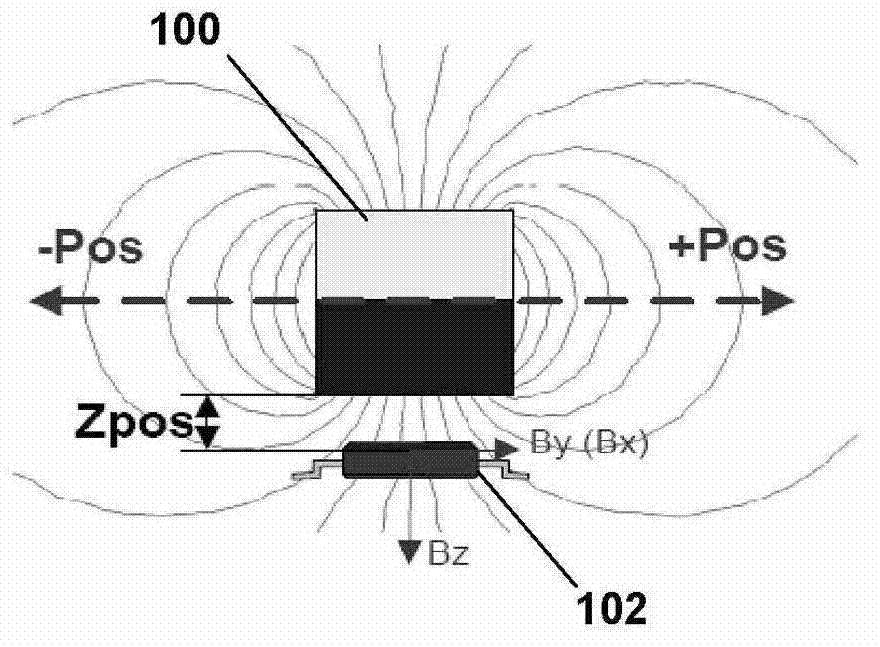
[0028] figure 1 A magnet 100 and a sensor system 102 configured to sense the position of the magnet are depicted. The magnet 100 is most commonly a source of a magnetic field and may in embodiments include a permanent magnet, an electromagnet, coil windings, or some other configuration. Such as figure 1 In the orientation in , the magnet is magnetized in the vertical (Z) direction and the sensor system 102 senses the linear position of the magnet 100 in the x-axis, but in other embodiments these directions and axes may be different. The specific axes, coordinate systems, and orientations used throughout this document are for example and convenience of illustration only and are not fixed in space. Instead, the x, y, and z axes are used to describe the three vertical axes of the axis system, which may be oriented in any spatial direction and which may be fixed, moving, and / or rotating relative to the earth's coordinate...


PUM


Abstract

Magnetic position sensors, systems and methods are disclosed. In an embodiment, a position sensing system includes a magnetic field source with a dipole moment in a direction along a z-axis; and a sensor module spaced apart from a center of the dipole moment a distance y0 along a y-axis and spaced apart a distance z0 from a center of the dipole moment along a z-axis, at least one of the magnetic field source or the sensor module configured to move relative to the other along a path in the y=y0 plane, the sensor module configured to determine a relative position of the magnetic field source to the sensor module with respect to the path from a ratio of a gradient dBz / dx to a gradient dBz / dy, where Bz is a magnetic field component associated with the permanent magnet, and where an x-axis, the y-axis and the z-axis are at right angles.

Description

technical field [0001] The present invention relates generally to sensors, and more particularly to magnetic position sensors. Background technique [0002] Magnetic sensors can be used for linear position sensing (ie, sensing the position of an object in one dimension) as well as multi-dimensional position sensing. A permanent magnet is attached to the target, and the magnetic field of the magnet is measured by a magnetic sensor. [0003] But conventional solutions for position sensing using magnetic sensors have some drawbacks. Some solutions do not have the ability to sense position in multiple dimensions. Other solutions are inaccurate and / or require complex mathematical calculations, which are difficult to perform with limited silicon area. [0004] Accordingly, improved magnetic position sensors, sensing systems and methods are needed. Contents of the invention [0005] Magnetic position sensors, systems and methods are disclosed. [0006] In one embodiment, a p...

Claims


Application Information

Patent Timeline
Patent Type & Authority Applications(China)
IPC IPC(8): G01D5/12
CPCG01D5/00G01R33/077G01R33/095G01D1/00G01R33/022G01D5/145G01B13/02G01D2205/40
Inventor 乌多·奥塞尔勒基纳费迪南德·卡斯汀格尔阿明·萨茨
Owner INFINEON TECH AG
Why Eureka
Try Eureka