Supercharge Your Innovation With Domain-Expert AI Agents!

Image forming apparatus

An image and toner image technology, which is applied in the field of image forming devices, can solve the problems of image fixing quality degradation, temperature instability of fixing roller 13, etc.

Inactive Publication Date: 2013-03-06
RICOH KK
View PDF5 Cites 2 Cited by
  • Summary
  • Abstract
  • Description
  • Claims
  • Application Information

AI Technical Summary

Problems solved by technology

[0004] In the prior art, the lower side of the fixing device 12 is covered by the lower side plate 17b of the image forming device 11, and its upper side and the rear side are not provided with any components, so the heat in the fixing device 12 will flow from the upper side and the rear side spread to the inside of the image forming device 11, making the temperature of the fixing roller 13 in the fixing device 12 unstable, resulting in a decrease in the quality of image fixing

Method used


Image

  • Image forming apparatus
  • Image forming apparatus
  • Image forming apparatus

Examples


Embodiment Construction

[0024] Hereinafter, preferred embodiments of the present invention will be specifically described with reference to the drawings.

[0025] The image forming apparatus in the present invention is, for example, a printer, a copier, a scanner, or the like.

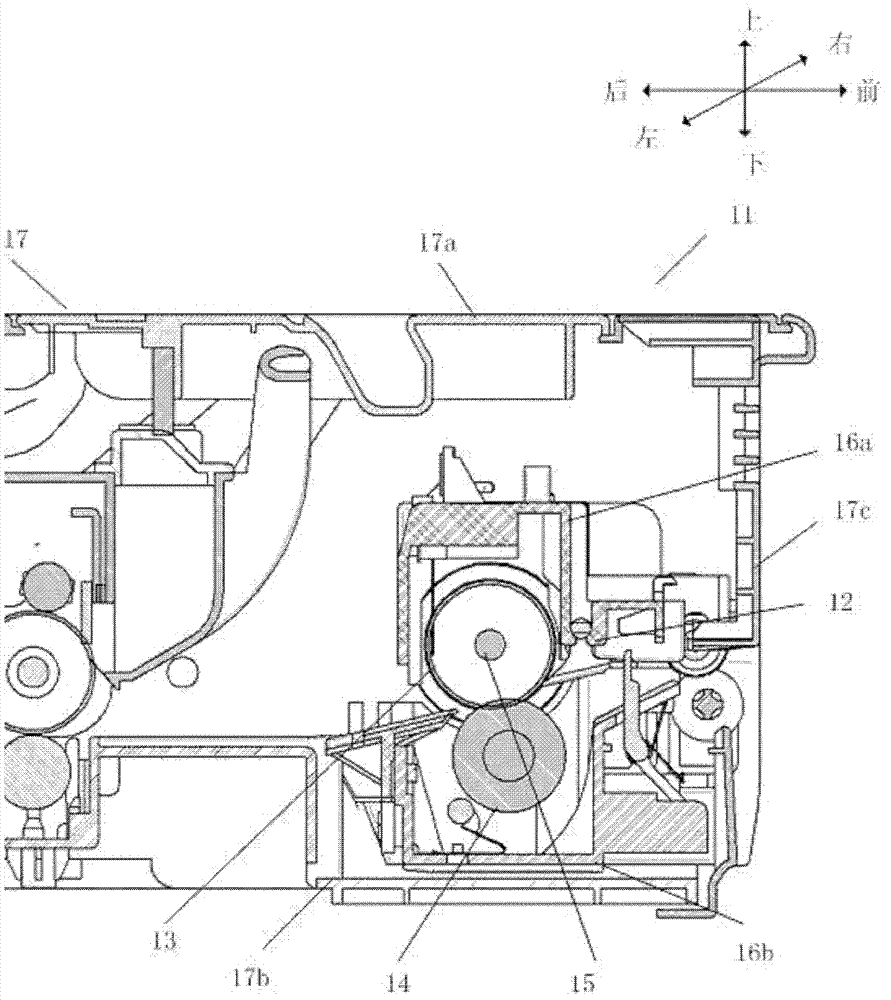
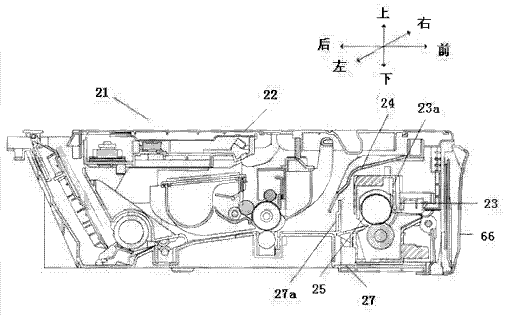
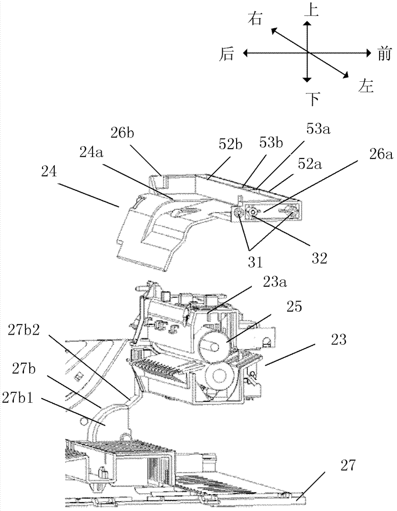
[0026] figure 2 is a sectional view showing an image forming apparatus mounted with a heat shield according to an embodiment of the present invention. image 3 is a partial perspective sectional view in an exploded state showing a heat shield, a fixing device, and a lower side plate according to an embodiment of the present invention, and can clearly show the positional relationship among them. Figure 4 is a partial sectional view showing an image forming apparatus mounted with a heat shield according to an embodiment of the present invention. Figure 5 is a partial perspective view showing an image forming apparatus mounted with a heat shield according to an embodiment of the present invention.

[0027] see Figure 2 t...


PUM


Abstract

The invention provides an image forming apparatus which comprises a housing; a fixing device which is used for heating and fixing toner images on a recording medium so as to form fixed images, and is located in the housing and at a front side of the image forming apparatus; and a thermal insulation plate which is located in the housing and at an upper side of the fixing device, and used for covering the upper side of the fixing device and at least a part of an upper rear side far away from a front side of the fixing device. Therefore, temperature of a fixing roller of the fixing device is enabled to be stable, image quality can be improved and energy can be saved.

Description

technical field [0001] The present invention relates to an image forming device, and more particularly to a heat shield used for a fixing device in the image forming device. Background technique [0002] Conventionally, image forming apparatuses using electrophotography are known technologies. For example, an electrostatic latent image is formed on the surface of a photosensitive drum as an image carrier, a recording medium such as paper is conveyed to pass under each photosensitive drum so that the toner image on the surface of the photosensitive drum is transferred onto the recording medium, Then, the toner image on the recording medium is fixed by a heating and pressurizing fixing device, and finally the fixed recording medium is discharged out of the image forming device through a discharge path. [0003] figure 1 A partial sectional view of the image forming apparatus 11 is shown, as figure 1 As shown, the image forming apparatus 11 has a housing 17 including an uppe...

Claims


Application Information

Patent Timeline
IPC IPC(8): G03G15/20G03G15/00
Inventor 姜乔都何军马挺
Owner RICOH KK
Features
  • R&D
  • Intellectual Property
  • Life Sciences
  • Materials
  • Tech Scout
  • Unparalleled Data Quality
  • Higher Quality Content
  • 60% Fewer Hallucinations
Learn More