Plasticizing screw for injection molding and injection molding method using same

A technology of injection molding and plasticizing screw, which is applied in the plasticizing screw for injection molding and the field of injection molding using the screw, which can solve the problems of uneven quality of thermoplastic resin, prevent uneven strength or weight, and prevent reinforcing fibers Exposure to the surface of molded products, the effect of improving the appearance

Active Publication Date: 2013-03-06
MITSUBISHI HEAVY INDS PLASTIC TECH
View PDF9 Cites 5 Cited by
  • Summary
  • Abstract
  • Description
  • Claims
  • Application Information

AI Technical Summary

Problems solved by technology

[0019] In this way, due to the fluctuation of the melting start position of the thermoplastic resin, there will be differences in the broken state, fiber opening, and dispersed state of the reinforcing fibers, so that the quality of the melted thermoplastic resin will be uneven.

Method used


Image

  • Plasticizing screw for injection molding and injection molding method using same
  • Plasticizing screw for injection molding and injection molding method using same
  • Plasticizing screw for injection molding and injection molding method using same

Examples


no. 1 approach

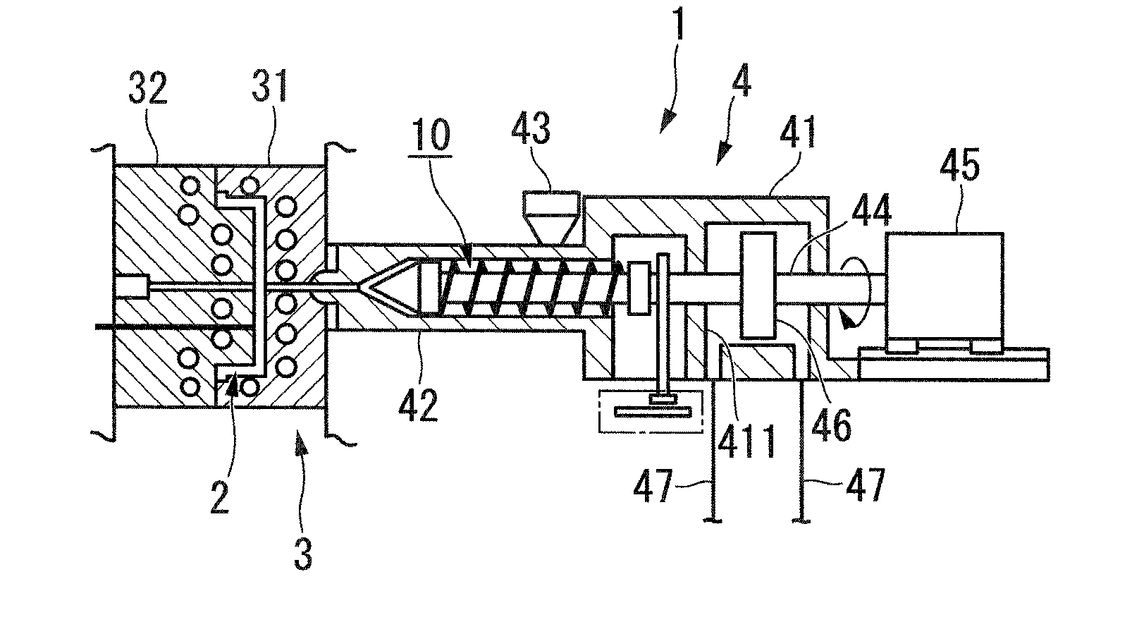
[0049] Hereinafter, embodiments of the present invention will be described with reference to the drawings. First, the structure of the plasticizing screw for injection molding according to the first embodiment of the present invention will be described. figure 1 It is a schematic diagram showing the overall structure of an injection molding machine 1 including a plasticizing screw 10 for injection molding (hereinafter, simply referred to as "screw 10") according to the first embodiment.

[0050] Such as figure 1 As shown, the injection molding machine 1 includes a mold unit 3 in which a cavity 2 is formed, and an injection unit 4 for injecting thermoplastic resin into the cavity 2 .

[0051] Such as figure 1 As shown, the die unit 3 includes a fixed die 31 provided so as not to move, and a movable die 32 provided so as to be movable relative to the fixed die 31 . Furthermore, the cavity 2 is formed between the concave portion of the fixed mold 31 and the convex portion of t...

no. 2 approach

[0068] Next, the configuration of the plasticizing screw 10 for injection molding (hereinafter, simply referred to as "screw 10") according to the second embodiment of the present invention will be described. The screw 10 of the second embodiment differs from the screw 10 of the first embodiment only in the structure of the secondary flight 15 . The configuration other than that is the same as that of the first embodiment, and thus the same reference numerals are used, and description thereof will be omitted here.

[0069] here, Figure 5 It is a developed view showing a region on the shaft 11 where the sub-thread 15 is provided. in addition, Figure 6 yes means Figure 5 A brief cross-sectional view of the B-B section in .

[0070] Like the sub-thread 15 of the first embodiment, the sub-thread 15 has a flat surface 151 provided at the rear end in the winding direction, and an inclined surface 152 provided so as to extend continuously from the front end of the flat surface...


PUM

PropertyMeasurementUnit
Dimension lengthaaaaaaaaaa
Lengthaaaaaaaaaa

Abstract

This plasticizing screw for injection molding is provided with a shaft, a main flight, and a sub-flight, and is installed in an injection molding machine that performs injection molding by plasticizing a thermoplastic resin starting material containing reinforcing fibers. The protrusion height of the main flight from the shaft peripheral surface is formed in a fixed manner at least at the region at which the sub-flight is provided. The sub-flight is provided with: a flat-surface section that is provided to the back-end side in the direction of winding and that has a protrusion height from the shaft peripheral surface that is fixed and lower than that of the main flight; and a tilted-surface section that is provided in a manner so as to extend continuously from the front end in the direction of winding of the flat-surface section, and that has a protrusion height from the shaft peripheral surface that gradually increases in the direction towards the front-end side in the direction of winding within a range that is lower than the main flight.

Description

technical field [0001] The present invention relates to a plasticizing screw for injection molding in which a main thread and a secondary thread protrude from the peripheral surface of a shaft, and an injection molding method using the plasticizing screw for injection molding. Background technique [0002] The injection molding mechanism that melts a raw material made of a thermoplastic resin and injects it into a mold has a screw housed inside the injection cylinder. In addition, as the screw, a screw in which one blade-shaped flight is provided in a helical shape on the peripheral surface of a shaft to be driven to rotate is widely used. According to such a screw, the solid thermoplastic resin raw material supplied into the injection cylinder receives a shear force from the rotating screw, is kneaded while being melted and plasticized, and is then injected into a mold. [0003] However, in recent years, a so-called twin-flight screw provided with two flights has been used...

Claims


Application Information

Patent Timeline
IPC IPC(8): B29C45/47B29C45/60B29K105/12
CPCB29C45/60B29C45/0005B29C45/47
Inventor 苅谷俊彦户田直树信田宗宏
Owner MITSUBISHI HEAVY INDS PLASTIC TECH
Why Eureka
Try Eureka