
Manufacturing methods for components made of composite materials

A composite material and component technology, which is applied to the components of pumping devices for elastic fluids, pump components, household components, etc., can solve the problem that the last layer of fibers is not very suitable.

Active Publication Date: 2016-08-03
SN DETUDE & DE CONSTR DE MOTEURS DAVIATION S N E C M A
View PDF6 Cites 0 Cited by
  • Summary
  • Abstract
  • Description
  • Claims
  • Application Information

AI Technical Summary

Problems solved by technology

From a mechanical strength point of view, this makes the final layer of fibers in these areas not very suitable

Method used


Image

  • Manufacturing methods for components made of composite materials
  • Manufacturing methods for components made of composite materials
  • Manufacturing methods for components made of composite materials

Examples


Embodiment Construction

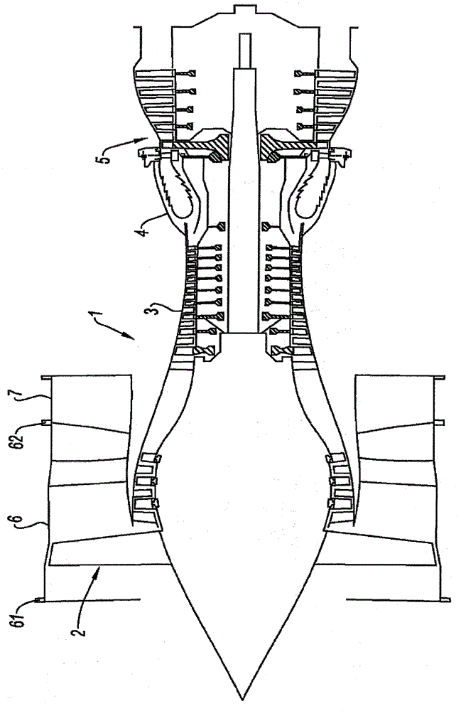
[0025] The invention applies to the manufacture of bypass turbojet fan casings, examples of which are figure 1 shown. The engine includes—from upstream to downstream, along the direction of gas flow—a front fan 2 at the engine inlet, an intake compressor, a high-pressure compressor 3, a combustion chamber 4, and high-pressure and low-pressure turbines 5 . The fan 2 is driven to rotate by a turbine (turbineBP) inside the fan case 6 . The fan case forms the volume of air that enters the engine interior. A portion of said air constitutes the main air flow, which is guided inside the engine to be successively compressed by the intake compressor and the high-pressure compressor. The air enters the combustion chamber 4 where its energy is enhanced by the combustion of fuel. The resulting gas is expanded in the subsequent turbine stage 5 and then injected. The other part of the air constitutes the auxiliary air flow, which is injected into the atmosphere directly or after meeting...


PUM


Abstract

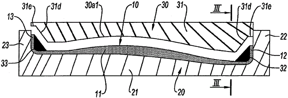
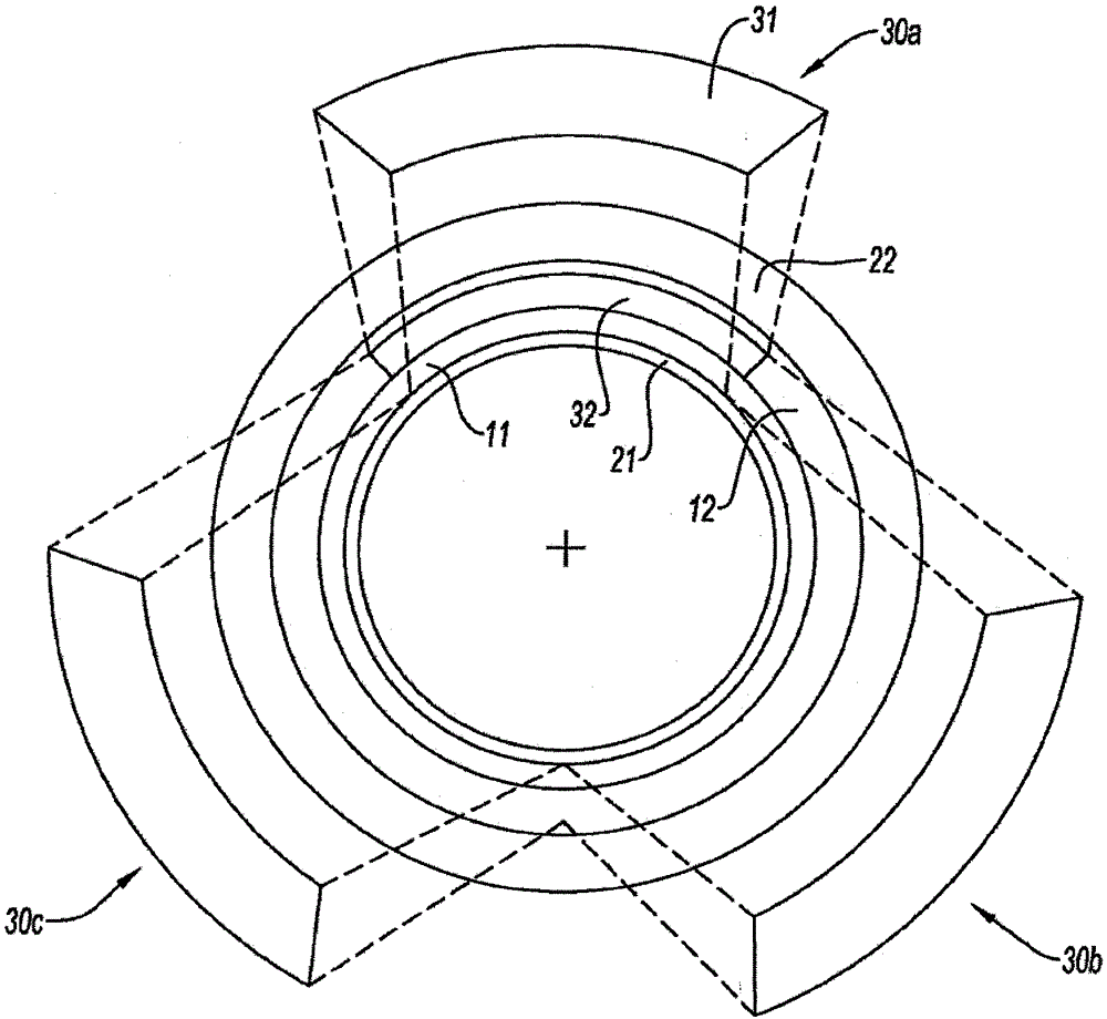
The invention relates to a method of manufacturing a part of composite material comprising a polymer substrate (20) reinforced with a fibrous structural member, said method comprising the steps of placing the fibrous structural member (10) in a molded surface formed On the substrate, the fibrous structure is covered with a matching mold (30), said fibrous structure is pressed by moving the matching mold towards the surface of the substrate. The method is characterized in that the base (20) comprises a cylindrical part (21) and walls (22, 23) fixed radially relative to the cylindrical part (21), and the matching mold comprises two parts (31, 32 or 33), the two parts move relative to each other and towards the axis of the cylindrical part (21) and towards the radial walls (22, 23) of the base (20). The invention may be particularly applicable to the manufacture of turbine engine fan cases.

Description

technical field [0001] The invention relates to the field of composite materials comprising a polymer matrix reinforced with a fibrous structure, and in particular to the use of such materials in the manufacture of aeroengine or turbine components. Background technique [0002] In the field of aviation, there is a need to reduce the weight of engine components while maintaining a high level of mechanical properties of these components. In multi-flow turbine engines, the fan case, which forms the shape of the air duct extending into the engine and houses the fan rotor inside, is currently made of composite materials. It consists of upstream and downstream ferrules with radial and transverse external flanges for connection and mounting to other parts of the engine, including the upstream air intake profile and the downstream intermediate case. The case supports the various components and should be able to keep objects from breaking off the fan blades. [0003] The method of ...

Claims


Application Information

Patent Timeline
Patent Type & Authority Patents(China)
IPC IPC(8): B29C70/46B29C70/54F04D29/52
CPCB29C33/22B29C33/306B29C70/46B29C70/543B29L2031/7504F04D29/023F04D29/526F04D29/542F05D2300/43F05D2300/603F05D2230/21B29C45/0005
Inventor 迈卡·古梅尔亚恩·马哈尔安东尼·菲利普
Owner SN DETUDE & DE CONSTR DE MOTEURS DAVIATION S N E C M A
Learn More