Lens unit

A lens unit and lens technology, applied in optical components, instruments, installation, etc., can solve the problems of difficult adjustment of lenses, inability to adjust lens spacing and inclination, difficulty in satisfying performance, etc., and achieve high-precision results

Inactive Publication Date: 2013-03-06
PANASONIC INTELLECTUAL PROPERTY CORP OF AMERICA
View PDF7 Cites 14 Cited by
  • Summary
  • Abstract
  • Description
  • Claims
  • Application Information

AI Technical Summary

Problems solved by technology

[0013] However, according to the method disclosed in Patent Document 1 and the methods disclosed in Patent Documents 2 and 3, the operability of adjusting the eccentricity of each lens is poor, and it is difficult to adjust the eccentricity of each lens with high precision.
There is a limit to reducing the decentering of each lens so that no adjustment is required
[0014] In addition, in recent years, more and more high-precision optical systems are required. If not only the eccentricity of the lenses, but also the distance and inclination between the lenses cannot be adjusted, it will be difficult to meet the performance requirements.

Method used


Image

  • Lens unit
  • Lens unit
  • Lens unit

Examples


Embodiment Construction

[0055] Hereinafter, embodiments of the lens unit of the present invention will be described.

[0056] First, while referring to Figure 1 to Figure 5 , while describing the overall configuration of the lens unit.

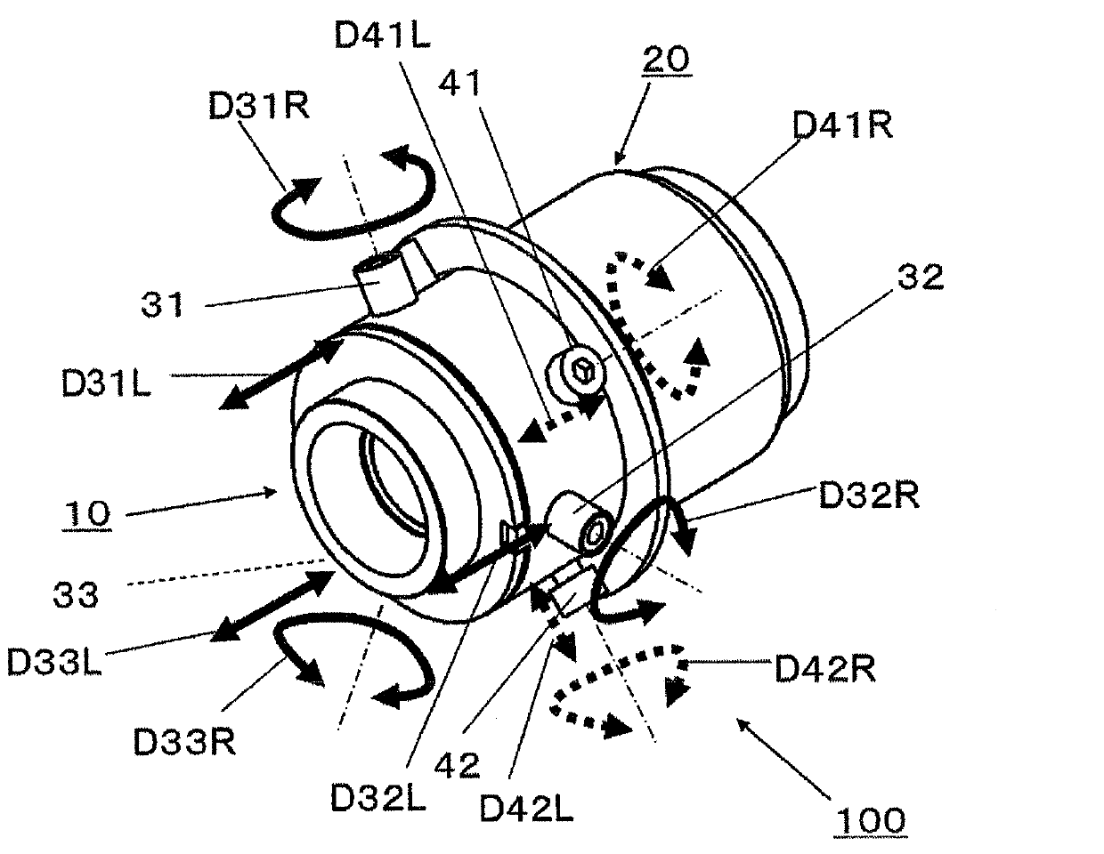
[0057] Such as figure 1 As shown, the lens unit 100 includes a first unit 10 and a second unit 20 .

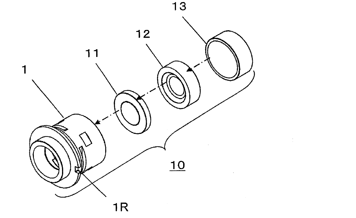
[0058] Such as figure 2 As shown, the first unit 10 includes: a first lens barrel 1 ; a first lens group inserted into the first lens barrel 1 , that is, a first lens 11 , a second lens 12 and a third lens 13 .

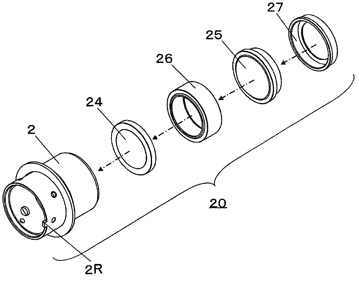
[0059] Such as image 3 As shown, the second unit 20 includes: the second lens barrel 2 ; the second lens group respectively inserted into the second lens barrel 2 , that is, the fourth lens 24 and the fifth lens 25 ; a spacer ring 26 ; and a lens seat ring 27 . The spacer ring 26 defines the interval between the fourth lens 24 and the fifth lens 25 . The lens holder 27 prevents the fourth lens 24 and the fifth lens 25 from coming out of the second ...


PUM


Abstract

Disclosed is a lens unit which comprises: first and second lens groups, each of which comprises at least one lens, and which have a focusing function by being arranged in series on the same optical axis; a first lens barrel (1) that holds the first lens group; a second lens barrel (2) that holds the second lens group and contains at least a part of the first lens barrel; and an adjustment mechanism for adjusting the first lens barrel and the second lens barrel with respect to the relative positions of the optical axis directions, the relative inclinations of the optical axes, and the relative eccentricities.

Description

technical field [0001] The present invention relates to a lens unit including a plurality of optical lenses, and particularly relates to a lens unit excellent in assemblability for use in imaging devices and the like. Background technique [0002] With the advancement of technology, digital still cameras (also referred to as digital cameras) are rapidly spreading, and mobile phones with cameras are becoming common. Therefore, there is an increasing demand for technology to realize a compact imaging device. In addition, in the photographing device, it is also required to achieve high image quality in captured images. [0003] In general, an imaging device includes a lens unit composed of a plurality of lenses in order to form an image on an imaging surface of an imaging element. The performance such as the resolution of the imaging device is largely determined by the design of the lens barrel of the lens unit, the accuracy of parts, the assembly accuracy when inserting the ...

Claims


Application Information

Patent Timeline
Patent Type & Authority Applications(China)
IPC IPC(8): G02B7/02
CPCG02B7/02G02B7/023G02B7/04
Inventor 江泽弘造泷泽辉之内田真司
Owner PANASONIC INTELLECTUAL PROPERTY CORP OF AMERICA
Why Eureka
Try Eureka