Injection mold

A technology for injection molds and mold cores, which is applied in the field of injection molds to achieve the effect of reducing costs

Active Publication Date: 2013-03-13
SHANTOU CHENGHAI JINGWEI IND
View PDF3 Cites 8 Cited by
  • Summary
  • Abstract
  • Description
  • Claims
  • Application Information

AI Technical Summary

Problems solved by technology

However, at present, steam injection molding i

Method used


Image

  • Injection mold
  • Injection mold
  • Injection mold

Examples


Embodiment Construction

[0023] It should be understood that the specific embodiments described here are only used to explain the present invention, not to limit the present invention.

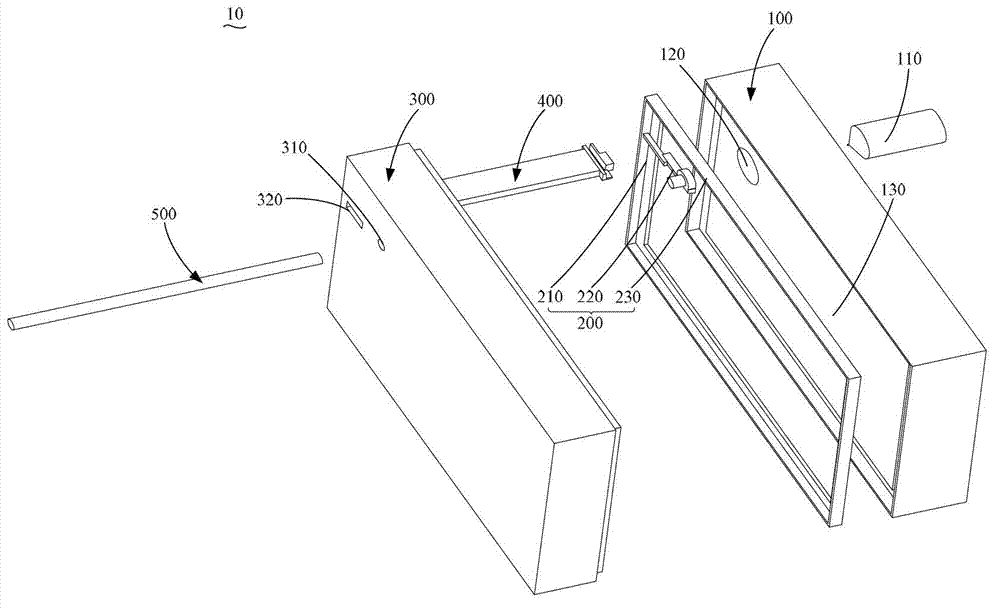
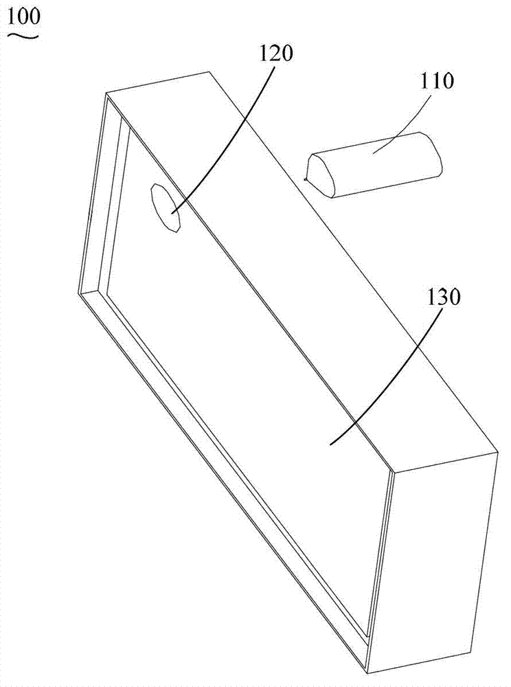
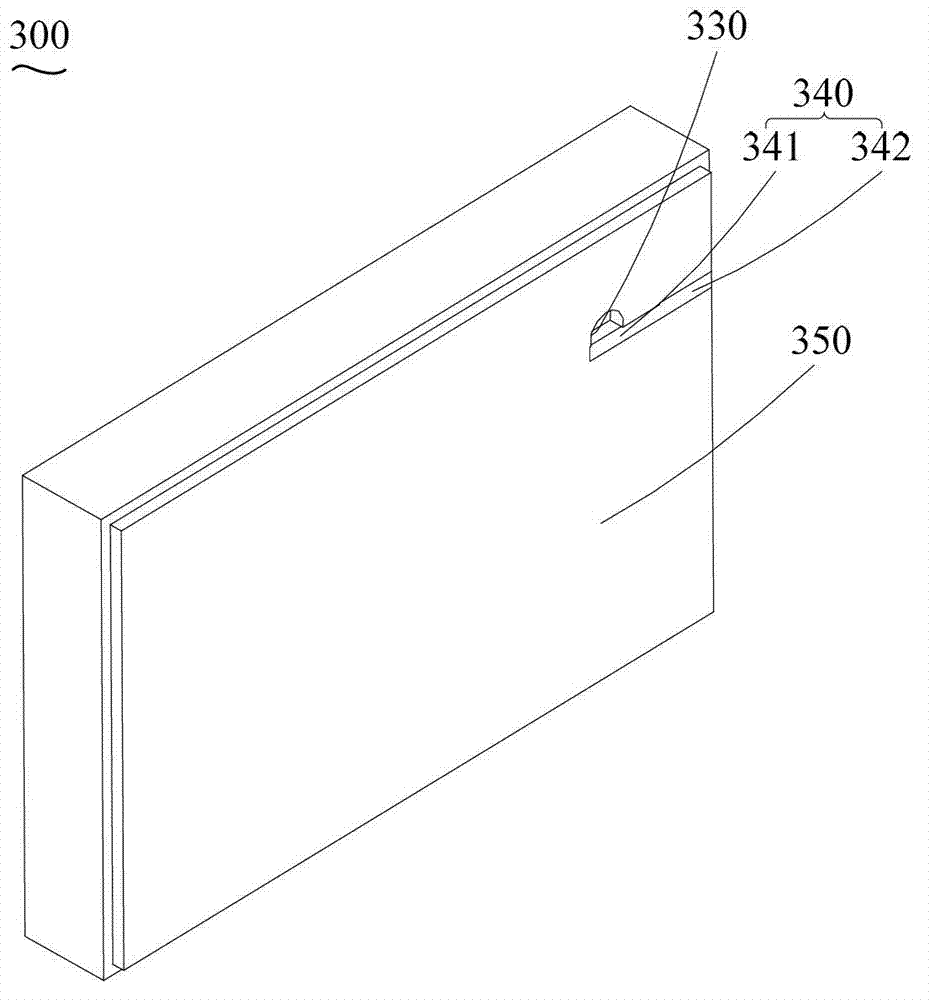
[0024] Please refer to figure 1 and image 3 , figure 1 It is a schematic diagram of the decomposition structure of a preferred embodiment of the injection mold of the present invention, image 3 for figure 1 Schematic diagram of the structure of the rear mold core of the injection mold shown. The injection mold 10 of the preferred embodiment of the present invention comprises a front mold core 100, a rear mold core 300 matched with the front mold core 100, and an ejection mechanism matched with the rear mold core 300, and the ejection mechanism includes The ejector pin 400 and the ejector pin 500, the front mold core 100 and the rear mold core 300 cooperate with each other to form a mold cavity. The rear mold core 300 is provided with a first groove 340, and the ejector pin 400 is inserted into the first groove ...


PUM


Abstract

The invention provides an injection mold. The injection mold comprises a front mold core, a rear mold core and an ejection mechanism, wherein the rear mold core is matched with the front mold core to form a mold cavity; the ejection mechanism is matched with the rear mold core and comprises an ejection rod; a first groove is formed in the rear mold core; and the ejection rod is embedded into the first groove and is matched with the front mold core to form a gating runner which is provided with a gating inlet formed in the inner side of the mold cavity. The injection mold is provided with the first groove, and the gating inlet formed in the inner side of a product through cooperation of the ejection rod and the front and rear mold cores, so that the influence of residual traces of a sprue gate on the appearance quality of the product can be avoided, and furthermore, since the residual traces of the sprue gate do not need to be repaired manually any more, production costs can be reduced while product yield is improved. Therefore, the injection mold is beneficial to implementation of mechanical operation.

Description

technical field [0001] The invention relates to an injection mold, in particular to an injection mold provided with a sprue on the inner side of a product. Background technique [0002] Injection molding (Injection Molding) refers to the method in which heated and melted materials are injected into the mold cavity from a state of high temperature, high pressure and high speed, and after cooling and solidification, plastic products can be obtained. This method is suitable for mass production of parts with complex shapes and is one of the important processing methods. The injection molding process can be roughly divided into the following six stages: "mold closing-injection-holding pressure-cooling-mold opening-product removal". The above process is repeated to continuously produce plastic products. [0003] At present, many plastic products need to ensure that the surface is smooth and flawless. For example, the frame of the display, the quality of the surface of the frame ...

Claims


Application Information

Patent Timeline
IPC IPC(8): B29C45/26B29C45/27B29C45/40
Inventor 陈国良王学敏
Owner SHANTOU CHENGHAI JINGWEI IND
Why Eureka
Try Eureka