Three-dimensional image display device, three-dimensional image display method, three-dimensional image display program, and recording medium

A technology of three-dimensional image and display device, which is applied in image communication, static indicators, cathode ray tube indicators, etc., and can solve problems such as eye fatigue

Inactive Publication Date: 2013-03-13
FUJIFILM CORP
View PDF6 Cites 7 Cited by
  • Summary
  • Abstract
  • Description
  • Claims
  • Application Information

AI Technical Summary

Problems solved by technology

therefore, Figure 13B Object B in , appears to protrude significantly from the display plane, causing fatigue to the user's eyes, as the user may be excessively esotropic

Method used


Image

  • Three-dimensional image display device, three-dimensional image display method, three-dimensional image display program, and recording medium
  • Three-dimensional image display device, three-dimensional image display method, three-dimensional image display program, and recording medium
  • Three-dimensional image display device, three-dimensional image display method, three-dimensional image display program, and recording medium

Examples


no. 1 example

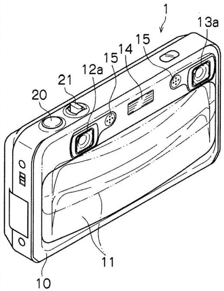
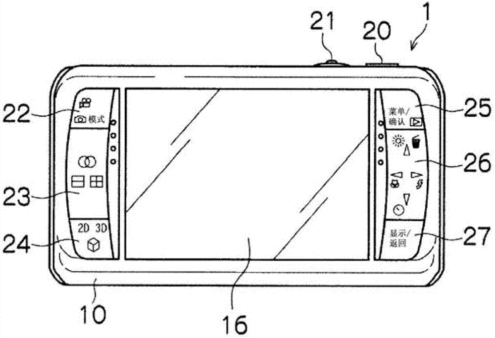
[0080] Figure 1A and Figure 1B is a schematic diagram of a compound eye digital camera 1 equipped with a three-dimensional image device according to the present invention. Figure 1A is its front view and Figure 1B is its rear view. Compound eye digital camera 1 is equipped with multiple (in Figure 1A and Figure 1B In the example of two) imaging systems, and can capture representations from multiple viewpoints (at Figure 1A and 1B In the example, a three-dimensional image (stereo image) of the same object observed from two viewpoints on the left and right), and a single viewpoint image (two-dimensional image) can be captured. The compound eye digital camera 1 can record and reproduce not only still images, but also moving images and sounds.

[0081] The camera body 10 of the compound eye digital camera 1 has a substantially rectangular parallelepiped shape, and as Figure 1A As shown in , a lens cover 11 , a right imaging system 12 , a left imaging system 13 , a ...

no. 2 example

[0193] In the first embodiment of the present invention, 2D processing is performed by superimposing and displaying the image of the target object in the image for left eye and deleting the target object from the image for right eye, but the 2D processing is not limited thereto.

[0194] The second embodiment of the present invention superimposes and displays the images of the target object in the left-eye image and the right-eye image as 2D processing. Hereinafter, the compound eye digital camera 2 of the second embodiment will be described. Those elements that are the same as those of the first embodiment are denoted by the same reference numerals, and descriptions thereof are omitted.

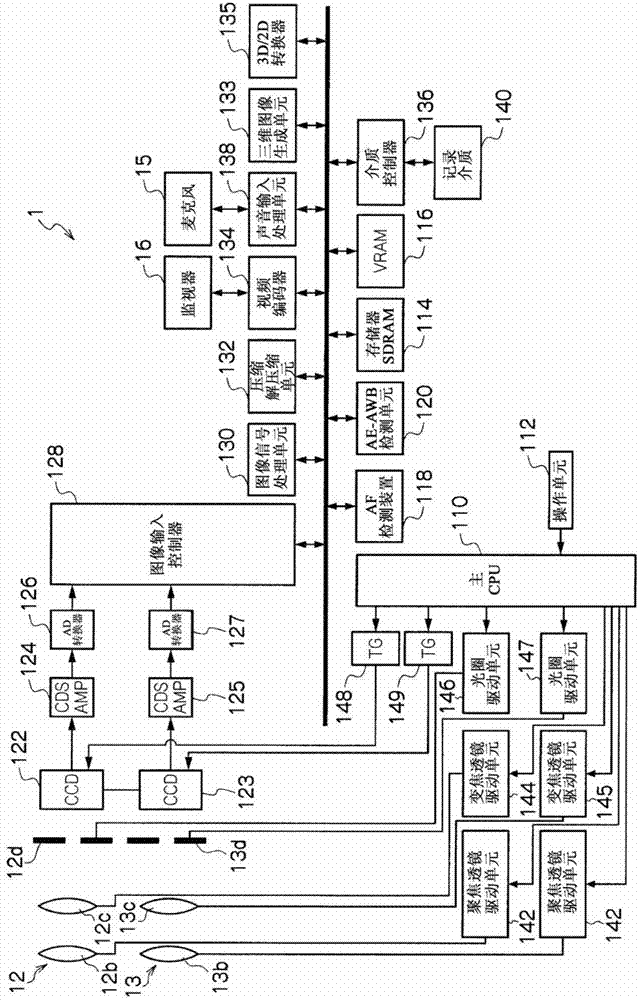
[0195] The main internal structure of the compound eye digital camera 2 will now be described. The 3D / 2D converter 135A is the only difference between the compound eye digital camera 2 and the compound eye digital camera 1 , so only the 3D / 2D converter 135A will be described.

[0196] Fi...

no. 3 example

[0220] In the second embodiment of the present invention, the target object processed to be translucent is composited to be superimposedly displayed in the image for left eye and the image for right eye, but the 2D processing is not limited thereto.

[0221] In the 2D processing of the third embodiment of the present invention, the photographed target object is processed to be translucent and the translucent image is synthesized so that the translucency of the target object is superimposed on the image for left eye and the image for right eye image. Hereinafter, the compound eye digital camera 3 of the third embodiment will be described. Those elements that are the same as those of the first embodiment and the second embodiment are denoted by the same reference numerals, and descriptions thereof are omitted.

[0222] The main internal structure of the compound eye digital camera 3 will now be described. The 3D / 2D converter 135B is the only difference between the compound eye...


PUM


Abstract

Among objects in front of a main subject, an object having a shift vector having a magnitude of a predetermined threshold value or more is determined as a target subject. The background image of a right-eye image is extracted from a left-eye image and is combined with the right-eye image, thereby removing the target subject from the right-eye image. Further, the target subject is combined at the position in the left-eye image corresponding to the position of the target subject in the right-eye image, thereby doubly displaying the target subject in the left-eye image. The right-eye image from which the target subject is removed and the left-eye image in which the target subject is doubly displayed are three-dimensionally displayed on a monitor (16). This enables the target subject not to be seen as a three-dimensional image. Furthermore, this enables a three-dimensional image to be displayed in consideration of the fatigue of user's eyes.

Description

technical field [0001] The present invention relates to a three-dimensional image display device, a three-dimensional image display method, a three-dimensional image display program, and a recording medium, and more specifically, to a three-dimensional image display device, a three-dimensional image display method, A three-dimensional image display program, and a recording medium. Background technique [0002] Examples of reproduction schemes for reproducing a three-dimensional image include a three-dimensional display device employing a parallax barrier system. The image for the left eye and the image for the right eye are respectively decomposed into strips in the direction perpendicular to the scanning direction of the image, and the decomposed strip images are arranged alternately to generate a single image. If the generated images are superimposed and displayed by extending the slit, the left-eye strip image can be visually recognized by the user's left eye, and the ri...

Claims


Application Information

Patent Timeline
Patent Type & Authority Applications(China)
IPC IPC(8): H04N13/00G09G5/36G09G5/377H04N5/225G03B35/18
CPCH04N13/0033G03B35/18H04N2013/0081H04N13/0018H04N13/0011H04N13/0022H04N13/0014H04N13/111H04N13/117H04N13/122H04N13/128H04N13/144
Inventor 中丸文雄
Owner FUJIFILM CORP
Why Eureka
Try Eureka