Scraper assembly for centrifugal machine

A centrifuge and scraper technology, applied to centrifuges and other directions, can solve the problems of increased cost and failure rate, complex structure of scraper components, and bloated centrifuge structure, and achieve the effect of simple structure, beautiful appearance and accurate action

Inactive Publication Date: 2013-03-20
张家港市轻工设备厂有限公司
View PDF4 Cites 6 Cited by
  • Summary
  • Abstract
  • Description
  • Claims
  • Application Information

AI Technical Summary

Problems solved by technology

The current centrifuges generally include a machine base, a shell fixed on the machine base, a spindle assembly installed on the machine base, and a drum arranged on the spindle assembly. The drum is located in the shell, and the bottom of the drum is provided with a discharge A drain channel is formed between the outer wall of the drum and the inner side of the housing. The main shaft assembly is driven by a motor assembly. A scraper assembly for scraping is installed on the housing. A rotary distributor is installed on the top of the housing. The scraper The structure of the components is relatively complicated. Generally, the scraper and the scraper need to go through multiple power transmissions to drive the scraper. Therefore, not only the structure of the whole centrifuge is bloated, but also the number of parts is increased, which increases the cost and failure rate.

Method used


Image

  • Scraper assembly for centrifugal machine

Examples


Embodiment Construction

[0013] The present invention will be described in further detail below through specific examples.

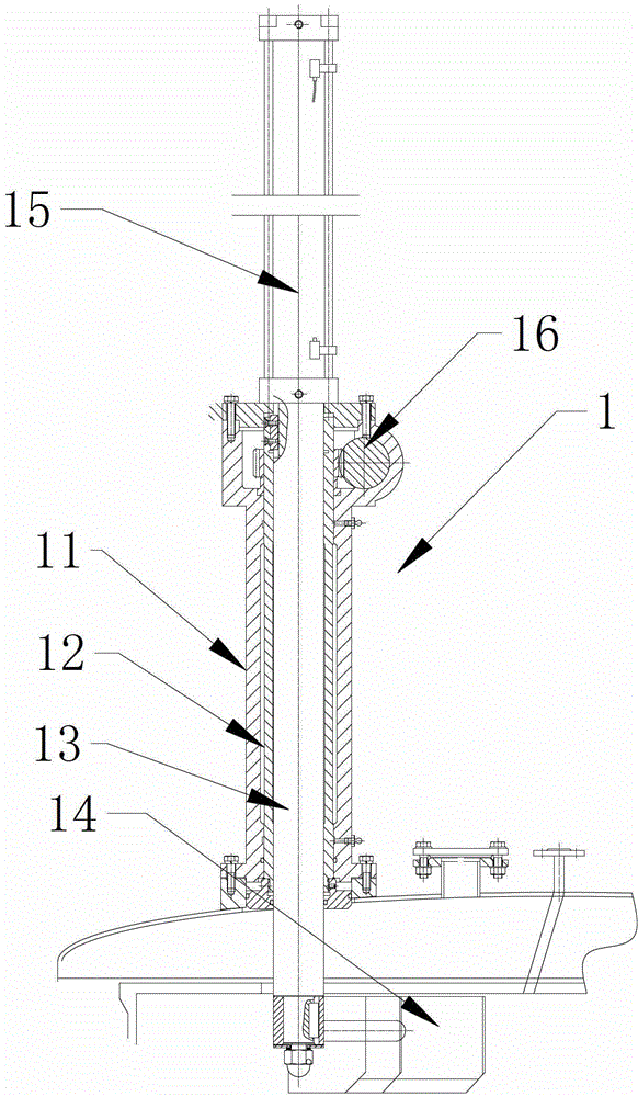
[0014] like figure 1 As shown, a centrifuge scraper assembly 1 includes an outer cylinder 11 vertically fixed on the top of the casing, a shaft sleeve 12 rotatably installed in the outer cylinder 11, a drive shaft 13 arranged in the shaft sleeve 12, and a The scraper 14 at the lower end of the drive shaft 13, the scraper 14 extends into the drum of the centrifuge, the sleeve 12 and the drive shaft 13 are connected by a sliding key, and the outer cylinder 11 is equipped with a drive shaft 13 to move vertically The axial power device, the sleeve 12 is driven by the rotary power device.

[0015] Wherein, the axial power device is preferably a cylinder 15, the cylinder 15 is installed on the top of the outer cylinder 11 and the piston rod of the cylinder 15 is connected to the drive shaft 13, further, the drive shaft 13 is the piston of the cylinder 15 pole. Of course, the axial ...


PUM


Abstract

The invention discloses a scraper assembly for a centrifugal machine. The scraper assembly comprises an outer cylinder which is fixed at the top of a casing vertically, a shaft sleeve installed inside the outer cylinder in a rotating manner, a driving shaft arranged inside the shaft sleeve and a scraper installed at the lower end of the driving shaft, wherein the scraper sticks into a rotary drum of the centrifugal machine, the shaft sleeve and the driving shaft are connected through a sliding key, an axial power device provided with a driving shaft moving vertically is installed on the outer cylinder, and the shaft sleeve is driven by a rotary power device. According to the scraper assembly for the centrifugal machine, stable and quick power transmission and accurate scraper motion are achieved.

Description

technical field [0001] The invention relates to a scraper assembly, in particular to a scraper assembly used for scraping materials on a centrifuge. Background technique [0002] The centrifuge uses the strong centrifugal force generated by the high-speed rotation of the drum to accelerate the sedimentation speed of the particles in the liquid and separate the substances with different sedimentation coefficients and buoyant densities in the sample. The current centrifuges generally include a machine base, a shell fixed on the machine base, a spindle assembly installed on the machine base, and a drum arranged on the spindle assembly. The drum is located in the shell, and the bottom of the drum is provided with a discharge A drain channel is formed between the outer wall of the drum and the inner side of the housing. The main shaft assembly is driven by a motor assembly. A scraper assembly for scraping is installed on the housing. A rotary distributor is installed on the top o...

Claims


Application Information

Patent Timeline
Patent Type & Authority Applications(China)
IPC IPC(8): B04B11/08B04B9/00B04B9/02
Inventor 王学明王平
Owner 张家港市轻工设备厂有限公司
Why Eureka
Try Eureka