Transmission assembly for lifting stand column and lifting stand column
A technology for lifting columns and assemblies, which is applied to lifting frames, lifting devices, etc., can solve problems such as affecting the user's use experience and easy to generate vibration, and achieve the effect of improving shock absorption, reducing force and smooth transmission.
- Summary
- Abstract
- Description
- Claims
- Application Information
AI Technical Summary
Problems solved by technology
Method used
Image
Examples
Embodiment 1
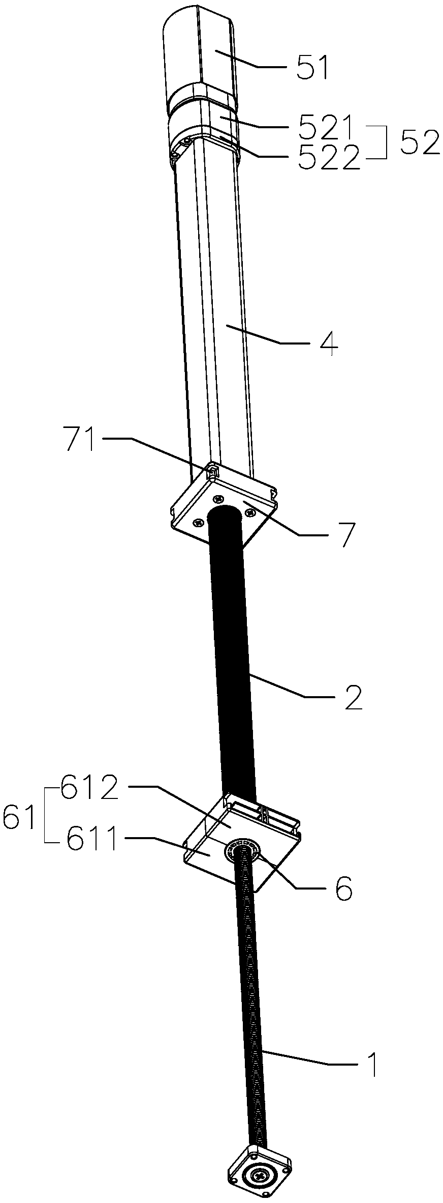
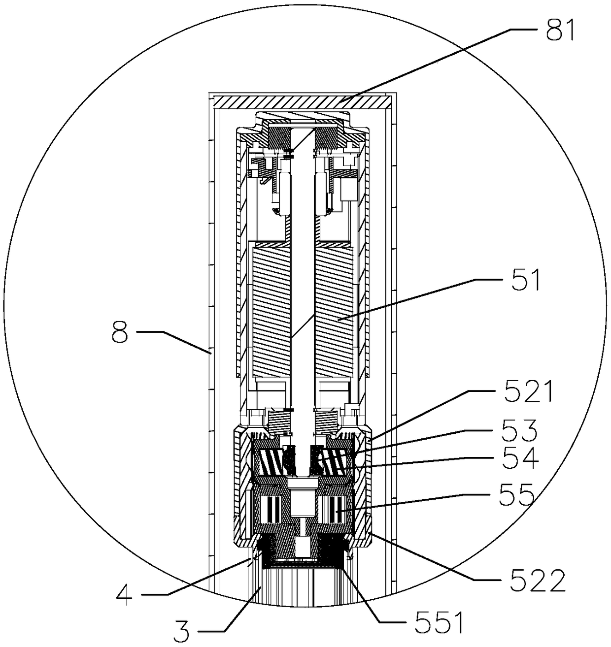
[0040] like Figure 1 to Figure 6 As shown, the present invention provides a transmission assembly for a lifting column. The lifting column includes an inner tube 8, and the transmission assembly includes a hollow shaft 2 provided with an external thread, a transmission screw 1 located in the hollow shaft 2, a sleeve A sleeve 4 outside the hollow shaft 2, a guide tube 3 rotatably limited in the sleeve 4, and a drive device 5 for driving the guide tube 3 to rotate, the guide tube 3 and the hollow shaft 2 can be synchronized Rotate and the guide tube 3 and the hollow shaft 2 can be relatively stretched along the axial direction, the transmission screw 1 can rotate synchronously with the hollow shaft 2 and the transmission screw 1 and the hollow shaft 2 can be relatively stretched along the axial direction, the driving device 5 is located at The inner tube 8 is fixedly installed on the upper end of the casing 4, the lower end of the casing 4 is fixedly connected with the first dr...
Embodiment 2
[0058] like Figure 8 As shown, the main difference between this embodiment and Embodiment 1 is that the top plate 81 is a flexible top plate, that is, the top plate is made of flexible materials. At this time, the driving device can be arranged without a gap between the flexible top plate, and the flexible top plate can buffer the driving device. vibration.
Embodiment 3
[0060] like Figure 9 As shown, the main difference between this embodiment and the first embodiment is that the transmission assembly further includes a middle pipe 10 , and the middle pipe 10 is located between the inner pipe 8 and the outer pipe 9 . The advantage of this setting is that the installation distance of the lifting column can be reduced by setting the three-section pipe for synchronous expansion and contraction.
[0061] In this embodiment, the lower end of the hollow shaft 2 is provided with a second drive nut 6 with a fixed circumferential position, and the second drive nut 6 is screwed with the drive screw 1, and the hollow shaft 2 is rotatably connected to the second drive nut. 6 is positioned in the axial direction, and the outside of the second drive nut 6 is provided with a lock structure 61 that limits the rotation of the second drive nut 6. The lock structure 61 is fixedly connected to the lower end of the middle tube 10, and the second drive nut 6 is p...
PUM
 Abstract
Description
Claims
Application Information
 - R&D
- Intellectual Property
- Life Sciences
- Materials
- Tech Scout
- Unparalleled Data Quality
- Higher Quality Content
- 60% Fewer Hallucinations
Browse by: Latest US Patents, China's latest patents, Technical Efficacy Thesaurus, Application Domain, Technology Topic, Popular Technical Reports.
© 2025 PatSnap. All rights reserved.Legal|Privacy policy|Modern Slavery Act Transparency Statement|Sitemap|About US| Contact US: help@patsnap.com


