Box having counting mechanism

A technology for controlling components and elastic components, which is applied in the fields of electrical recording technology using charge graphics, equipment for using electrical recording technology using charge graphics, and electrical recording technology. question

Pending Publication Date: 2018-05-29
JIANGXI YIBO E TECH CO LTD
View PDF8 Cites 3 Cited by
  • Summary
  • Abstract
  • Description
  • Claims
  • Application Information

AI Technical Summary

Problems solved by technology

[0004] The invention provides a box with a counting mechanism to solve the technical problems in the prior art that the structure of the counting mechanism in the box is complex due to the use of tooth-missing gears and the manufacturing precision of the tooth-missing gears is high

Method used


Image

  • Box having counting mechanism
  • Box having counting mechanism
  • Box having counting mechanism

Examples


no. 1 example

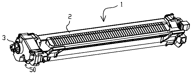
[0035] Such as figure 1 As shown, the cartridge 1 of the present invention includes: a housing 2 for accommodating developer; an input gear 3 disposed on one side of the housing 2, which can be engaged with a drive head in an image forming device to receive the driving of the image forming device Force; the counting mechanism 50 on the same side as the input gear 3, which can be detected by the detection unit in the image forming device. Optionally, since the detection unit in the image forming device can be arranged in any area relative to the box installed in the image forming device, the counting mechanism 50 matched with the detected unit in the image forming device may also be arranged on the box and Input gear 2 is not on the same side as the rest of the area.

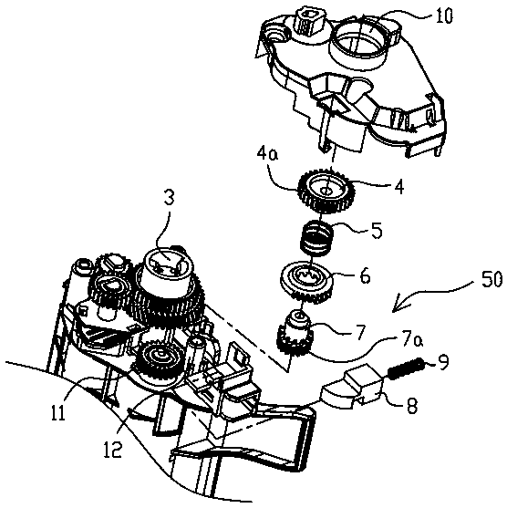
[0036] Such as figure 2 As shown, the housing 2 includes the first transmission gear 4 on the same side as the input gear 3 , which can transmit the driving force to the counting mechanism 50 . In this embodi...

no. 2 example

[0043] Such as Figure 11 to Figure 14 shown. The difference between this embodiment and the first embodiment lies in that the detected part and the control mechanism for controlling the movement of the detected part in this embodiment are different from those in the first embodiment. In this embodiment, the detected portion 81 cooperates with the information detection mechanism in the image forming apparatus by rotating and moving. In this embodiment, the detected part 81 is provided with a force receiving part 81a and a torsion spring positioning groove 81b, the control member 61 is provided with a force application part 61a, and the housing is provided with a second mounting post 22, the second mounting post 22 is close to The bottom end of the casing is provided with a stopper 22a, the detected part 81 is installed on the second mounting column 22, and the third elastic member 82 is arranged between the casing and the detected part 81. The third elastic member 82 in this ...


PUM


Abstract

The present invention discloses a box capable of being detachably arranged in an image forming apparatus having a detection unit. The box comprises: a housing, an input gear and a counting mechanism,wherein the counting mechanism comprises a detected part capable of changing the state of a detection body, the driving force from the input gear can be transmitted to the detected part so as to makethe detected part move between a first position and a second position, the first position is a position at where the detected part changes the state of the detection body, the second position is a position at where the detected part does not change the state of the detection body, the input gear transmits driving force to the detected part to make the detected part move from the first position tothe second position, the driving force transmitted to the detected part by the input gear can be disconnected at the second position, and the detected part can move from the second position to the first position when the driving force is disconnected, which solves the problem in the prior art. The lack of toothed gears has made the manufacturing cost of the box a technical problem.

Description

technical field [0001] The invention relates to cassettes with counting mechanisms. Background technique [0002] In the image forming devices of the prior art (printers, copiers and facsimile machines, etc.), a box with a counting mechanism detachably installed on the image forming device is widely used, through the information detection mechanism on the image forming device and the counting on the box The mechanism enables detection of whether the cartridge mounted thereto is a new cartridge, thereby determining the lifetime of the cartridge. [0003] Chinese Patent Publication No. CN104487903A discloses a box with a technical mechanism. The counting mechanism is provided with a detected gear. The driving force is transmitted to the missing gear so that the missing gear can rotate at a certain angle, and the detection process of the cartridge is realized by pressing and unpressing the detecting part in the image forming device during the rotation of the missing gear. The...

Claims


Application Information

Patent Timeline
Patent Type & Authority Applications(China)
IPC IPC(8): G03G15/08
CPCG03G15/0863
Inventor 胡亮亮敖仕平姜鹏皮艳军
Owner JIANGXI YIBO E TECH CO LTD
Why Eureka
Try Eureka