Positioning structure for turbine blade blank
A technology for positioning structure and turbine blades, which is used in manufacturing tools, forging/pressing/hammer devices, forging/pressing/hammering machines, etc., and can solve the problems of uneven material flow, low material utilization, and low service life. , to achieve the effect of reducing energy consumption, improving production efficiency, and reducing temperature drop
Inactive Publication Date: 2013-03-20
WUXI TURBINE BLADE
View PDF6 Cites 4 Cited by
- Summary
- Abstract
- Description
- Claims
- Application Information
AI Technical Summary
Problems solved by technology
[0003] In view of the above problems, the present invention provides a positioning structure for the blank of the turbine blade, which can solve the problem of uneven material flow and low material utilization rate of the blank during the die forging process due to the absence of an effective positioning device in the forging die. problem, and can effectively reduce the problem of low service life of the mold due to wear, while reducing production energy consumption and improving production efficiency
Method used
View moreImage
Smart ImageViewing Examples
Examples
Embodiment Construction
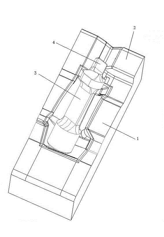
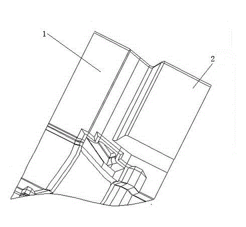
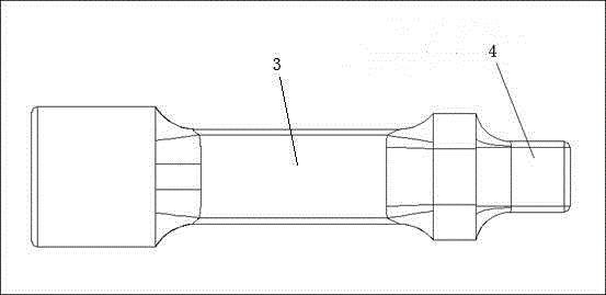
[0009] See you figure 1 , figure 2 with image 3 , The structure of the present invention includes a forging die 1. A shelf 2 is provided at the outer end of the crown cavity of the forging die 1 cavity, and a positioning strap 4 is provided on the top of the blank 3 to be processed. The blank 3 is placed on the forging die 1. In the cavity, the positioning strap 3 is limited by the material storage platform 2.
Login to View More PUM
 Abstract
The invention provides a positioning structure for a turbine blade blank, which can be used for solving the problems of non-uniform material flow and low material utilization ratio of a blank in a die forging process due to the absence of an effective positioning device for die forging of the conventional blank, can be used for effectively solving the problem of short service life caused by wear of a die, and contributes to lowering the production energy consumption and increasing the production efficiency. The positioning structure is characterized by comprising a forging die, wherein a material carrying table is arranged on the end part of the outer side of a leaf-crown-shaped cavity of a lower die forging module; a positioning lug is arranged on the top of a blank to be processed; the blank is arranged in the die cavity of the forging die; and the positioning lug of the blank is limited by using the material carrying table.
Description
Technical field [0001] The invention relates to the technical field of die forging of turbine blades, in particular to the positioning structure of a turbine blade blank. Background technique [0002] The blank is a transition between the bar and the forging, and the placement of the blank in the mold cavity has a greater impact on the final forming result of the forging. In actual production, the size difference of the same batch of blanks is often encountered but the forging The size of the later forgings is quite different, which is often determined by the positioning of the blank in the mold cavity. For blade forgings, especially for moving blades, there is usually no corresponding positioning measures in the design of the blank and die, which results in uneven material flow during the forging process, especially for the large twist angle of the blade crown and blade root. Even if damping is added to the easy-flow side of the mold cavity, the blank positioning effect cannot ...
Claims
Login to View More Application Information
Patent Timeline
 Patent Type & Authority Applications(China)
IPC IPC(8): B21J13/08
Inventor 徐烽陈鹏
Owner WUXI TURBINE BLADE
Features
- R&D
- Intellectual Property
- Life Sciences
- Materials
- Tech Scout
- Unparalleled Data Quality
- Higher Quality Content
- 60% Fewer Hallucinations
Learn More Browse by: Latest US Patents, China's latest patents, Technical Efficacy Thesaurus, Application Domain, Technology Topic, Popular Technical Reports.
© 2025 PatSnap. All rights reserved.Legal|Privacy policy|Modern Slavery Act Transparency Statement|Sitemap|About US| Contact US: help@patsnap.com


