Workpiece aligning and conveying apparatus

A technology for arranging conveying devices and workpieces, applied in the direction of conveyors, vibrating conveyors, conveyor objects, etc., can solve the problems of direct input, transportation, and production line efficiency reduction of improper postures of workpieces, and achieve the effect of reducing posture transformation errors

Inactive Publication Date: 2013-03-20
SHINKO ELECTRIC CO LTD
View PDF5 Cites 12 Cited by
  • Summary
  • Abstract
  • Description
  • Claims
  • Application Information

AI Technical Summary

Problems solved by technology

[0007] Usually, workpieces having such posture change errors are excluded in the inspection step, but when many posture change errors occur, it is not possible to continuously transport workpieces with appropriate postures to the next process. It will cause the efficiency of the whole production line to decrease
In addition, if it cannot be eliminated in the inspection step, the workpiece may be directly input to the next process with an inappropriate posture, causing other serious problems

Method used


Image

  • Workpiece aligning and conveying apparatus
  • Workpiece aligning and conveying apparatus
  • Workpiece aligning and conveying apparatus

Examples


no. 1 Embodiment approach

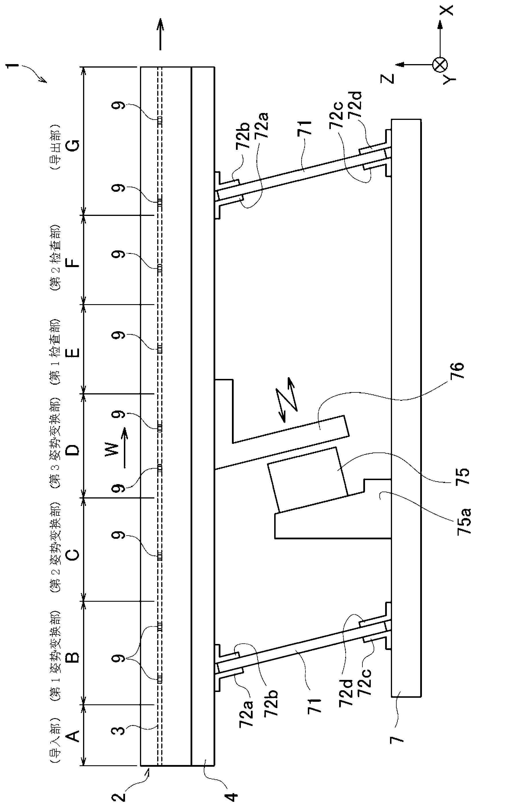
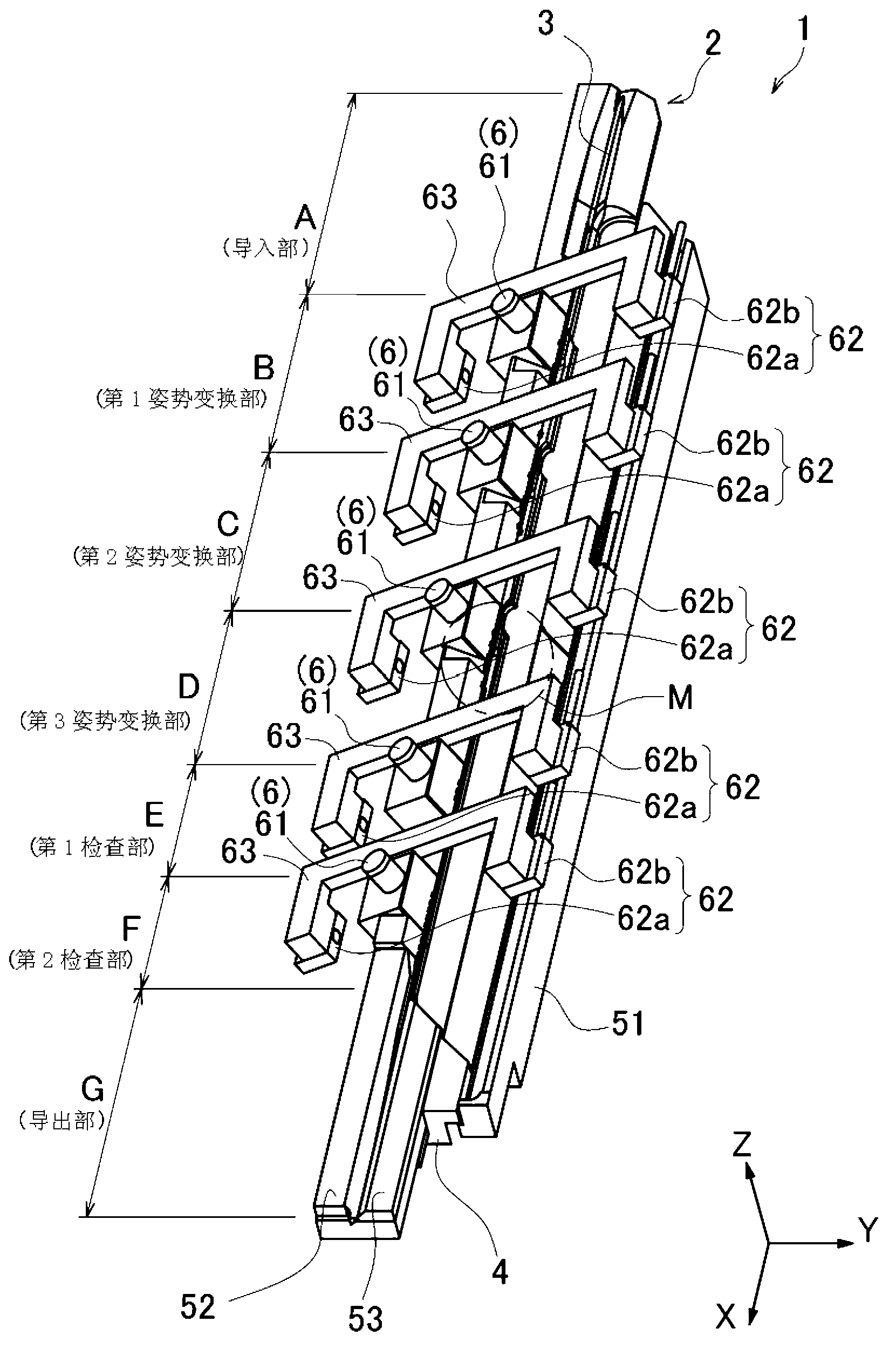
[0037] Such as figure 1As shown, the workpiece alignment and conveyance device 1 according to the first embodiment is configured to vibrate the conveyance table 2 on which the conveyance path 3 is formed, and can be conveyed and placed on the conveyance table 2 in the W direction in the drawing by utilizing the vibration of the conveyance table 2 . Workpieces 9-9 above.

[0038] Here, the conveying direction of the workpiece 9 is defined as the W direction, the horizontal direction substantially the same as the conveying direction of the workpiece 9 is defined as the X direction, and the vertically upward direction is defined as the Z direction as the coordinate axes shown in the figure. direction, the inward direction of the paper surface orthogonal to the X direction and the Z direction is defined as the Y direction.

[0039] Hereinafter, the specific structure of the workpiece alignment conveyance apparatus 1 of this embodiment is demonstrated using each direction defined ...

no. 2 Embodiment approach

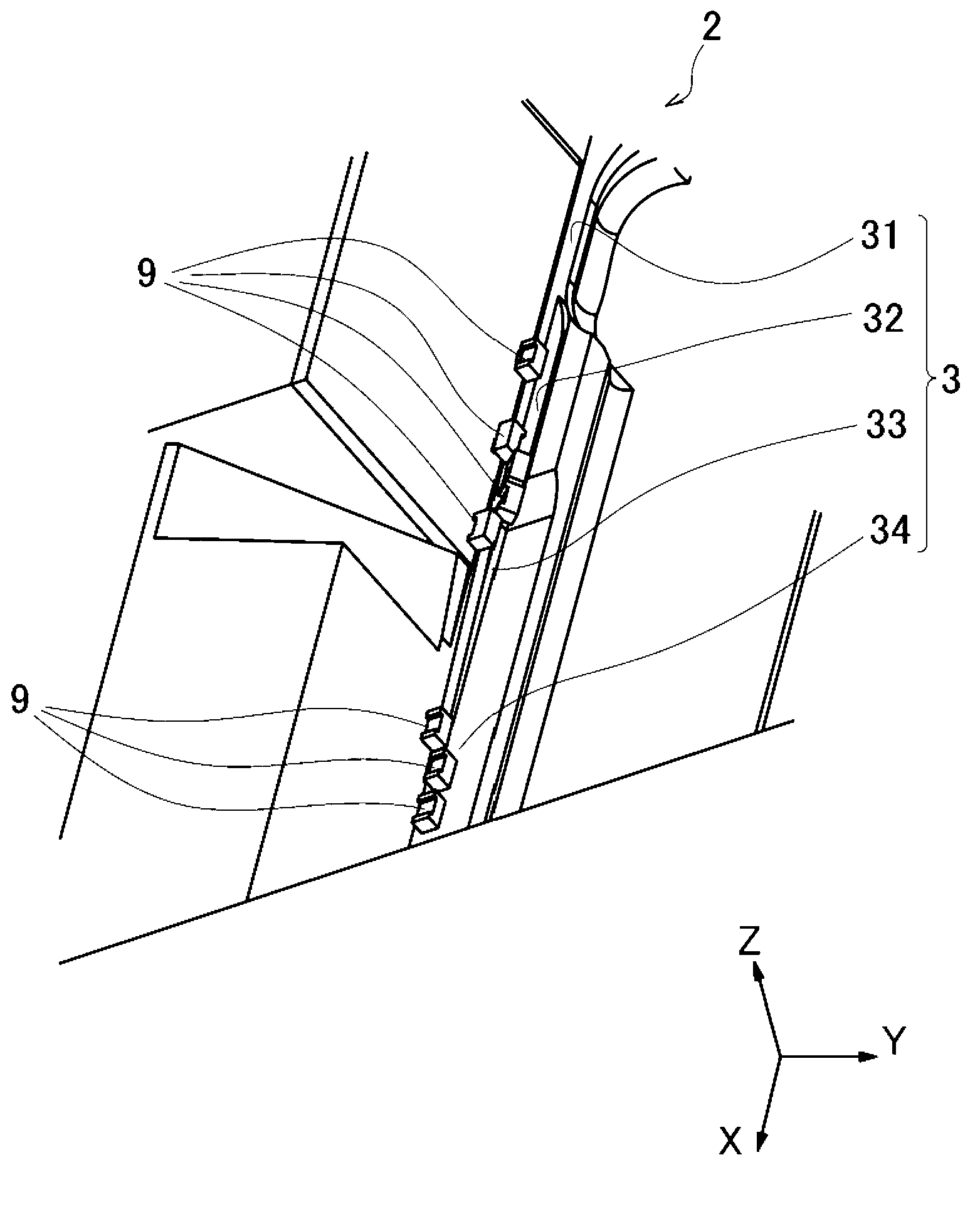
[0103] Figure 12 It is a perspective view showing the vicinity of the junction J1 ( 34 ) of the workpiece alignment and conveyance device 1 according to the first embodiment, Figure 13 It is a perspective view showing the vicinity of the junction J2 ( 134 ) of the workpiece array conveyance device 101 according to the second embodiment of the present invention.

[0104] The workpiece array conveyance apparatus 101 of the second embodiment is different from the workpiece array conveyance apparatus 1 of the first embodiment only in the form of the confluence part J1 ( J2 ), and other parts are the same as the workpiece array conveyance apparatus 101 of the first embodiment. 1 is the same. Therefore, the same reference numerals are assigned to the same parts as those in the first embodiment, and descriptions of parts other than the junction J2 are omitted. Additionally, if Figure 12 and Figure 13 As shown, the lengths in the transport direction of the junction J1 of the f...


PUM


Abstract

A workpiece aligning and conveying apparatus (1) reducing gesture changing errors of the workpiece is provided, and the apparatus enables the workpiece (9) to move along a conveying path (3) formed on a conveying bench (2), and the apparatus can simultaneously enable the workpiece (9) to rotate around an axial line parallel to a conveying direction, and a preset gesture is formed, the conveying path (3) comprises: a first conveying path (31) with a cross section of a general V shaped groove; a middle conveying path (32) parallel to the first conveying path, the middle conveying path has a cross section of a general V shaped groove, and an opening direction of the groove is reversely arranged, and the opening direction starts from inclining to a first conveying path side and stops when the opening direction is generally the same with an opening direction of the first conveying path; a second conveying path (33) parallel to the first conveying path, and the second conveying path has a cross section of a general V shaped groove, the groove is continuously arranged with the middle conveying path in a conveying direction, groove opening direction is generally the same with the opening direction of the first conveying path, and a conveying path(3) is provided with a joining portion (34) enabling the first conveying path and the second conveying path to be gradually closed and then jointed.

Description

technical field [0001] The present invention relates to a workpiece alignment and conveyance device for conveying supplied workpieces while aligning them in a predetermined orientation. Background technique [0002] Conventionally, many techniques have been disclosed for continuously supplying workpieces in a production line of a factory and conveying them while aligning the postures of the workpieces. [0003] For example, in Patent Document 1, a workpiece alignment and conveyance device is disclosed. The workpiece alignment and conveyance device is a linear feeder, which can rotate workpieces different from a predetermined orientation while conveying workpieces in one direction. Parallel axes are rotated to align the orientation of the workpiece. In this workpiece alignment and conveying device, the workpiece is conveyed in one direction along the first conveying path (first rail) by vibration, and the posture of the workpiece during conveying is detected. When the postur...

Claims


Application Information

Patent Timeline
Patent Type & Authority Applications(China)
IPC IPC(8): B65G47/24
CPCB65G27/12B65G47/14B65G47/1421B65G47/1428B65G47/19B65G2203/0283B65G2203/042
Inventor 迎邦晓山本贤犬井智三
Owner SHINKO ELECTRIC CO LTD
Why Eureka
Try Eureka