Counterweight system for elevator with tractor ratio of 4:1

A traction ratio and elevator technology, which is applied to elevators in buildings, lifting equipment in mines, transportation and packaging, and can solve problems such as high cost, complex structure, and poor versatility

Active Publication Date: 2013-03-20
宁波申菱机电科技股份有限公司
View PDF7 Cites 0 Cited by
  • Summary
  • Abstract
  • Description
  • Claims
  • Application Information

AI Technical Summary

Problems solved by technology

[0004] The disadvantage of the above-mentioned design is that the former elevator counterweight device is not suitable for elevators with a traction ratio of 4:1. The design of a new type of elevator counterweight device has a complicated structure, high cost, and the shaft depth (the shaft depth It refers to the length of the shaft perpendicular to the side of the elevator door in the top view of the shaft, that is to say, the length of the shaft in the direction perpendicular to the elevator door) is required to be large, compared with the 2:1 traction ratio of the traditional machine room. The holes in the machine room and the layout of the load-bearing beams are quite different, and the versatility is not strong

Method used


Image

  • Counterweight system for elevator with tractor ratio of 4:1
  • Counterweight system for elevator with tractor ratio of 4:1

Examples


Embodiment Construction

[0012] The present invention will be further described below in conjunction with accompanying drawing.

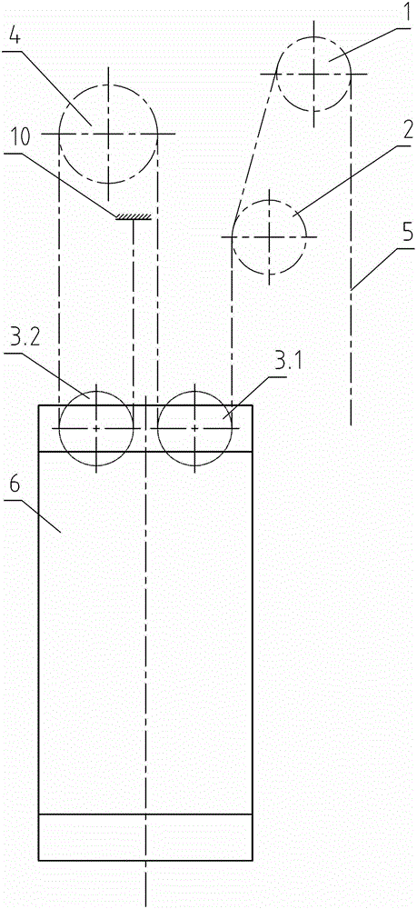
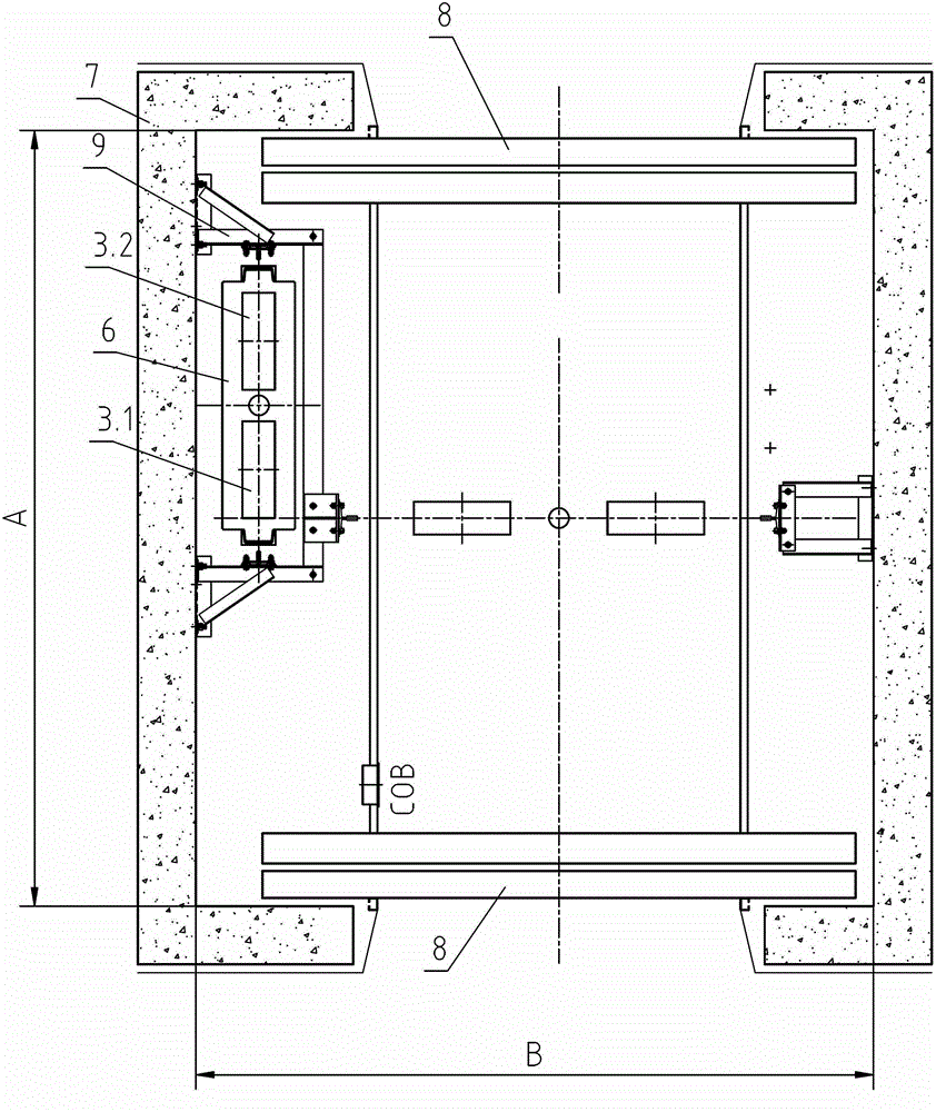
[0013] The elevator counterweight system with a traction ratio of 4:1 in the present invention includes a counterweight guide wheel 4, a first counterweight reversing sheave 3.1, a second counterweight reversing sheave 3.2 and a counterweight body 6, the first counterweight reversing The rope wheel 3.1 and the second counterweight anti-sheave 3.2 are installed on the counterweight body 6, and the traction rope 5 enters from the first counterweight anti-sheave 3.1, and then passes through the counterweight guide wheel 4 to the second counterweight anti-rope pulley. Sheave 3.2 goes out and is connected to fixed rope end 10, and described fixed rope end 10 is positioned between the second counterweight reverse rope wheel 3.2 and counterweight guide wheel 4, and described fixed rope end 10 is positioned at counterweight guide wheel 4 Projecting downward.

[0014] The second co...


PUM


Abstract

The invention discloses a counterweight system for an elevator with a tractor ratio of 4:1, which can reduce the size of a counterweight in the depth direction of a hoistway, thereby especially being suitable for the arrangement of a car through door of the elevator with a tractor ratio of 4:1 and the elevator with a tractor ratio of 4:1 with a small car hoistway depth. The counterweight system comprises a counterweight guide wheel (4), a first pair of counterweight diversion sheaves (3.1), a second pair of counterweight diversion sheaves (3.2) and a counterweight body (6), wherein the first pair of counterweight diversion sheaves (3.1) and the second pair of counterweight diversion sheaves (3.2) are arranged on the counterweight body (6), and a traction rope (5) enters from the first pair of counterweight diversion sheaves (3 .1) to the second pair of counterweight diversion sheaves (3.2) through the counterweight guide wheel (4) and is connected to a fixed rope end (10) which is positioned between the second pair of counterweight diversion sheaves (3.2) and the counterweight guide wheel (4) and positioned in the downward projection of the counterweight guide wheel (4).

Description

technical field [0001] The invention relates to the technical field of elevator counterweight systems, in particular to an elevator counterweight system with a traction ratio of 4:1. Background technique [0002] Elevator counterweight system, also known as elevator balance system, is one of the indispensable important components of modern traction elevators. The main function of this system is to relatively balance the weight of the side of the car. The weight difference of the counterweight is kept within the limit to ensure the normal traction drive of the elevator and the safety of the elevator. Due to its importance, the design and layout of the counterweight has also become one of the important areas in the design of the elevator system. [0003] For an elevator with a traction ratio of 4:1, due to its own inherent characteristics, its counterweight device is obviously different from the traditional elevator. For example, the name is: elevator counterweight device, and...

Claims


Application Information

Patent Timeline
Patent Type & Authority Applications(China)
IPC IPC(8): B66B11/04B66B17/12
Inventor 罗刚军童安全侯胜欣
Owner 宁波申菱机电科技股份有限公司
Why Eureka
Try Eureka