RH vacuum chamber baking system

A vacuum chamber and baking device technology, which is applied to casting melt containers, manufacturing tools, metal processing equipment, etc., can solve the problems of unfavorable temperature rise in the lower part of the vacuum chamber, difficulty in heating the lower part of the vacuum chamber, and the heating speed cannot be too fast. Avoid heat loss, shorten drying and baking time, and ensure baking speed and effect

Inactive Publication Date: 2013-03-20
WISDRI ENG & RES INC LTD
View PDF6 Cites 7 Cited by
  • Summary
  • Abstract
  • Description
  • Claims
  • Application Information

AI Technical Summary

Problems solved by technology

The existing technology uses a baking gun to bake, and can adjust the height of the baking gun to bake different parts of the vacuum chamber, so that the temperature of the upper and lower parts of the vacuum chamber is consistent, but the mechanism is relatively complicated and the investment in equipment is high. High failure rate
When using a roaster for baking, since the nozzle of the roaster is fixed, it is not conducive to the temperature rise of the lower part of the vacuum chamber
Especially for newly built vacuum chambers, the heating rate should not be too fast during the drying process, otherwise the moisture in the refractory materials will not be separated out. At this time, the baking waste gas often escapes from the upper part of the vacuum chamber, making it difficult to heat up the lower part of the vacuum chamber.
In addition, when baking at high temperature, the baking waste gas is directly discharged from the insertion tube at the bottom of the vacuum chamber, which deteriorates the site environment, and there is also continuous heat radiation to the surrounding equipment and steel structures.

Method used


Image

  • RH vacuum chamber baking system
  • RH vacuum chamber baking system
  • RH vacuum chamber baking system

Examples


Embodiment 1

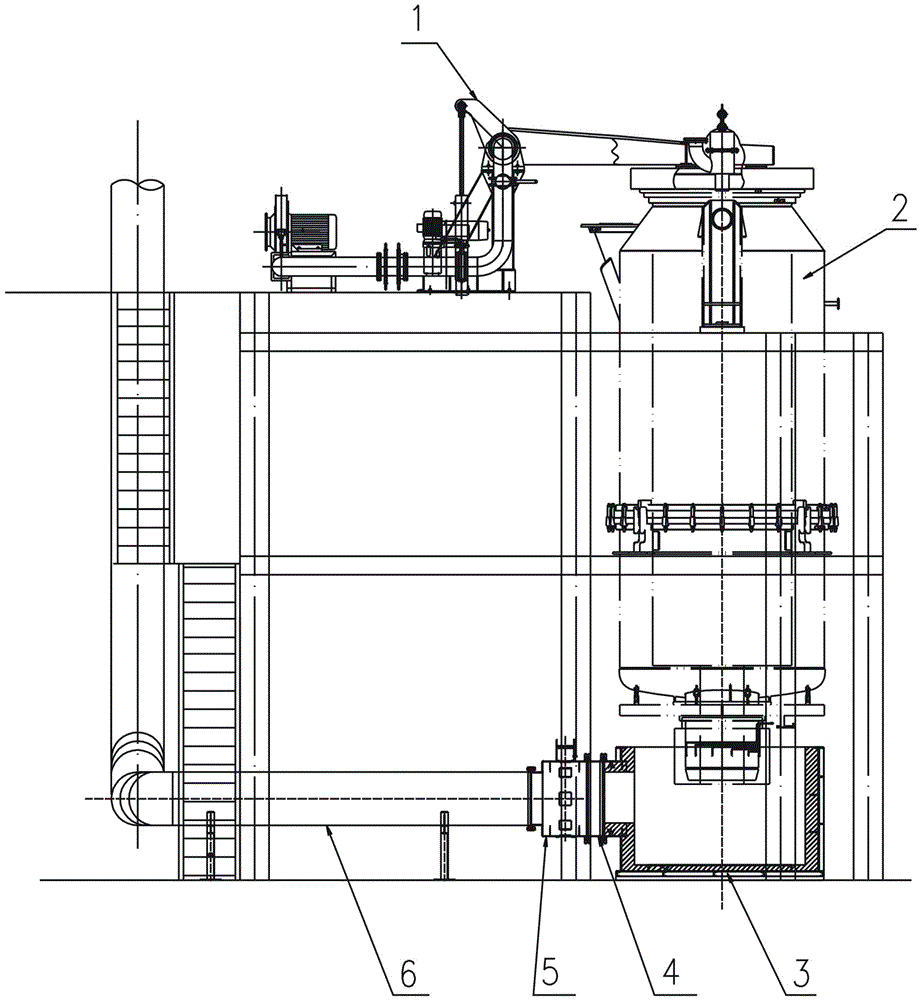
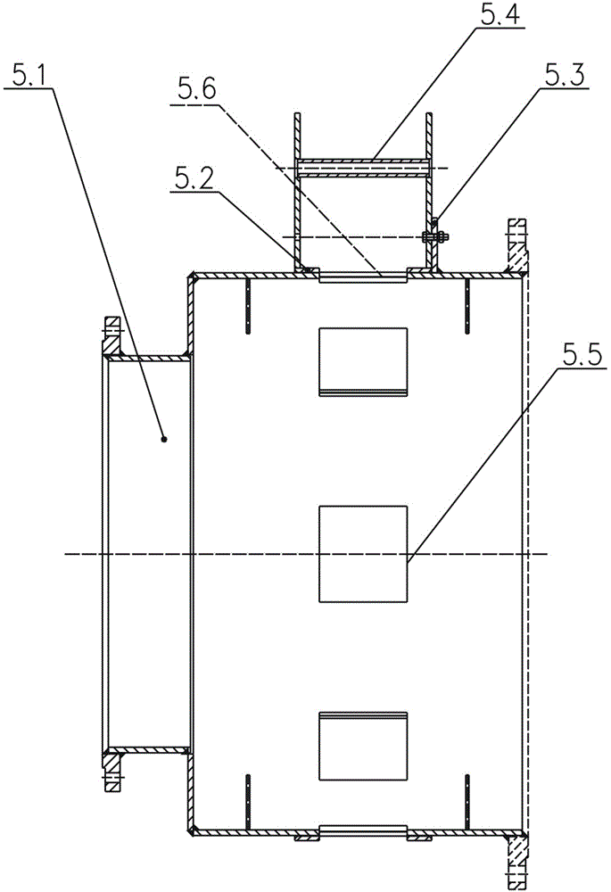
[0029] Such as figure 1 , 2 As shown, a RH vacuum chamber baking system includes a vacuum chamber baking device 1 and a vacuum chamber 2. A baking cover is arranged on the vacuum baking device 1. The cover plate is sealed with the upper part of the vacuum chamber. To prevent the baking heat from escaping. The lower part of the vacuum chamber insertion tube is sealed with the exhaust gas box 3, the exhaust gas box 3 is provided with an exhaust port, the exhaust port of the exhaust gas box 3 is connected with the air mixing device 5 through the control valve 4, and the air mixing device 5 is connected with the exhaust gas pipeline. 6 connections.

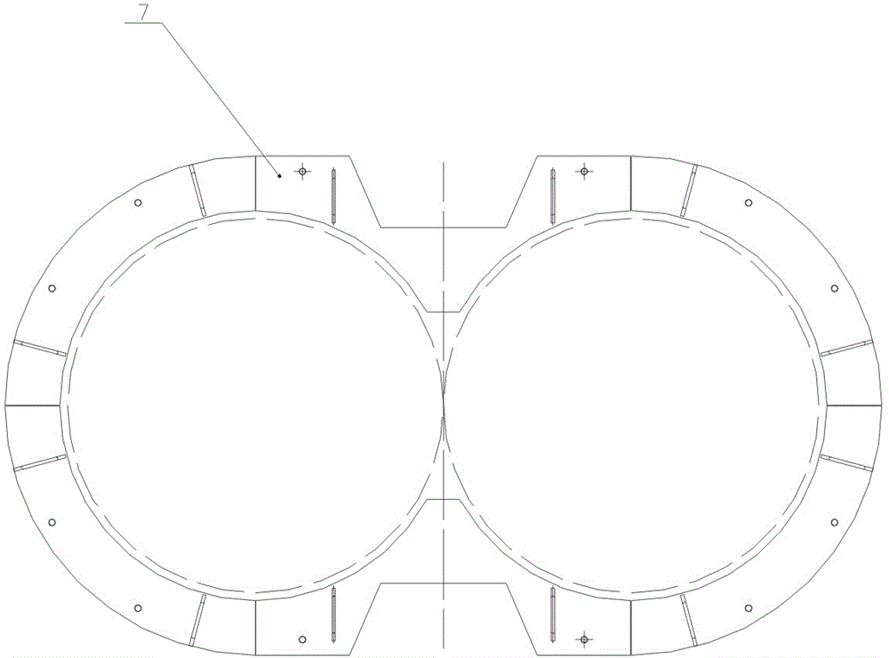
[0030] In this embodiment, the exhaust gas box is a fixed exhaust gas box, which includes a fixed exhaust gas box body and a cover plate 7. The fixed exhaust gas box body and the cover plate are respectively provided with refractory material linings. The structure diagram of the cover plate 7 is as follows image 3 shown. This kin...

Embodiment 2

[0037] Such as Figure 4 As shown, the structure of embodiment 2 is basically the same as that of embodiment 1. The difference lies in the structure of the exhaust gas box 3. Since the vacuum trolley can only make the vacuum chamber move in translation, in order to adapt to different working conditions on site, the exhaust gas box 3 can be designed Into a movable exhaust gas box to meet the needs of different working conditions. The exhaust gas box 3 in this embodiment comprises a left exhaust gas box 8 and a right exhaust gas box 9, the left and right exhaust gas boxes are symmetrically arranged, and when the left and right exhaust gas boxes are connected together, they are configured with the vacuum chamber insertion tube, Both sides of the exhaust gas box are provided with guide rails 10, and both sides of the left exhaust gas box 8 and the right exhaust gas box 9 are equipped with guide wheels to cooperate with the guide rails 10, so that the left exhaust gas box 8 and the...

Embodiment 3

[0040] Such as Figure 5 , 6 As shown, the structure of embodiment 3 is basically the same as that of embodiment 2, the difference lies in the structure of the exhaust gas box. The exhaust gas box includes an exhaust gas box 13 with a square opening on one side, a movable shutter 14 and a cover plate 7, and the movable shutter 14 is hinged to the bottom of the exhaust gas box 13 through a U-shaped hinge block 15, A cylinder 17 is arranged obliquely below the outside of the exhaust gas box 13, and the piston rod 16 of the cylinder is hinged to the outside of the movable shutter 14. By controlling the expansion and contraction of the piston rod 16, the opening of the exhaust gas box 13 and the movable shutter 14 The ends are merged into an exhaust gas box, and the cover plate 7 is sealed with the insertion tube of the vacuum chamber. The vacuum chamber baking system composed of the movable exhaust gas box can be set at the maintenance position or the standby position, and it i...


PUM

PropertyMeasurementUnit
heightaaaaaaaaaa

Abstract

The invention discloses a RH vacuum chamber baking system which comprises a vacuum chamber baking device and a vacuum chamber, wherein the vacuum chamber baking device is provided with a baking cover; the baking cover is matched with the upper part of the vacuum chamber; a vacuum chamber insert tube is connected with a waste gas box; the waste gas box is provided with an exhaust port; the exhaust port of the waste heat box is connected with an air mixer through a control valve; and the air mixer is connected with a waste gas duct. By arranging the baking cover and control valve, in the vacuum chamber drying process, the opening of the control valve is reduced, the retention time of baking hot gas in the vacuum chamber is prolonged, the loss of heat is avoided maximally, and the heating of the baking waste gas on the lower part of the vacuum chamber can be effectively controlled, thereby promoting the temperature uniformity of the refractory material in the vacuum chamber; and in the vacuum chamber baking process, the control valve can be adjusted to control the flow rate of the waste gas by utilizing the draft formed by the chimney effect of the waste gas duct, thereby ensuring the baking speed and baking quality of the vacuum chamber.

Description

technical field [0001] The invention relates to the field of vacuum metallurgy, in particular to a RH vacuum chamber baking system. Background technique [0002] In recent years, as end users have higher and higher requirements for steel quality, the proportion of vacuum refining of molten steel has become higher and higher. RH vacuum smelting has good kinetic characteristics and outstanding metallurgical effect, and has been basically popularized in major steel mills in recent years. [0003] In the prior art, the RH vacuum treatment has a processing position and a standby position, the vacuum chamber is produced at the processing position, and the vacuum chamber is hoisted and baked at the standby position. After the RH vacuum chamber refractory material is built, it needs to be dried and heated by a baking device before being placed on the treatment site. The existing technology uses a baking gun to bake, and can adjust the height of the baking gun to bake different par...

Claims


Application Information

Patent Timeline
Patent Type & Authority Applications(China)
IPC IPC(8): C21C7/10B22D41/015
Inventor 王逸名李智许海虹成剑明许畅张钟蓓陈海周
Owner WISDRI ENG & RES INC LTD
Why Eureka
Try Eureka