Electric power tool including a plurality of circuit boards

a circuit board and power tool technology, applied in the field of electric power tools, can solve the problems of reducing the measures to protect the electronic components from heating, the heat of the switching element is not easily conducted to the electronic components, etc., and achieves the effect of increasing the length of the electric power tool and reducing the heat protection measures

Active Publication Date: 2014-08-19
MAKITA CORP
View PDF22 Cites 26 Cited by
  • Summary
  • Abstract
  • Description
  • Claims
  • Application Information

AI Technical Summary

Benefits of technology

[0009]According to the first aspect of the present invention, the switching element is arranged inside the grip portion, and is spaced apart from the electronic circuit board for the electronic component for operating the switching element. As a result, the heat of the switching element is not easily conducted to the electronic component, making it possible to reduce the measures for protecting the electronic component from heating.
[0010]Further, since the switching element is arranged inside the grip portion, there is no need to provide a space for the switching element behind the DC brushless motor, thereby preventing an increase in the entire length of the electric power tool.
[0013]According to the present invention, both end edges of the power circuit board to which the switching element is attached are supported by the inner wall surface of the grip portion. As a result, the contact area between the power circuit board and the grip portion can be reduced, making it limited for the heat of the switching element to be conducted to the grip portion.
[0014]Further, since the board surface of the power circuit board is oriented substantially in the same direction as the board surface of the motor board attached to an end surface of the DC brushless motor, no twisting is generated in a plurality of power lines connecting the power circuit board (the switching element) and the motor board (the DC brushless motor), thereby making the wiring space to be compact.
[0019]According to the present invention, the switching element is arranged inside the grip portion so as to be spaced apart from an electronic component such as a microprocessor, whereby it is possible to reduce the heat protection measures for the electronic component without involving an increase in the entire length of the electric power tool.

Problems solved by technology

As a result, the heat of the switching element is not easily conducted to the electronic component, making it possible to reduce the measures for protecting the electronic component from heating.

Method used


Image

  • Electric power tool including a plurality of circuit boards
  • Electric power tool including a plurality of circuit boards
  • Electric power tool including a plurality of circuit boards

Examples


embodiment 1

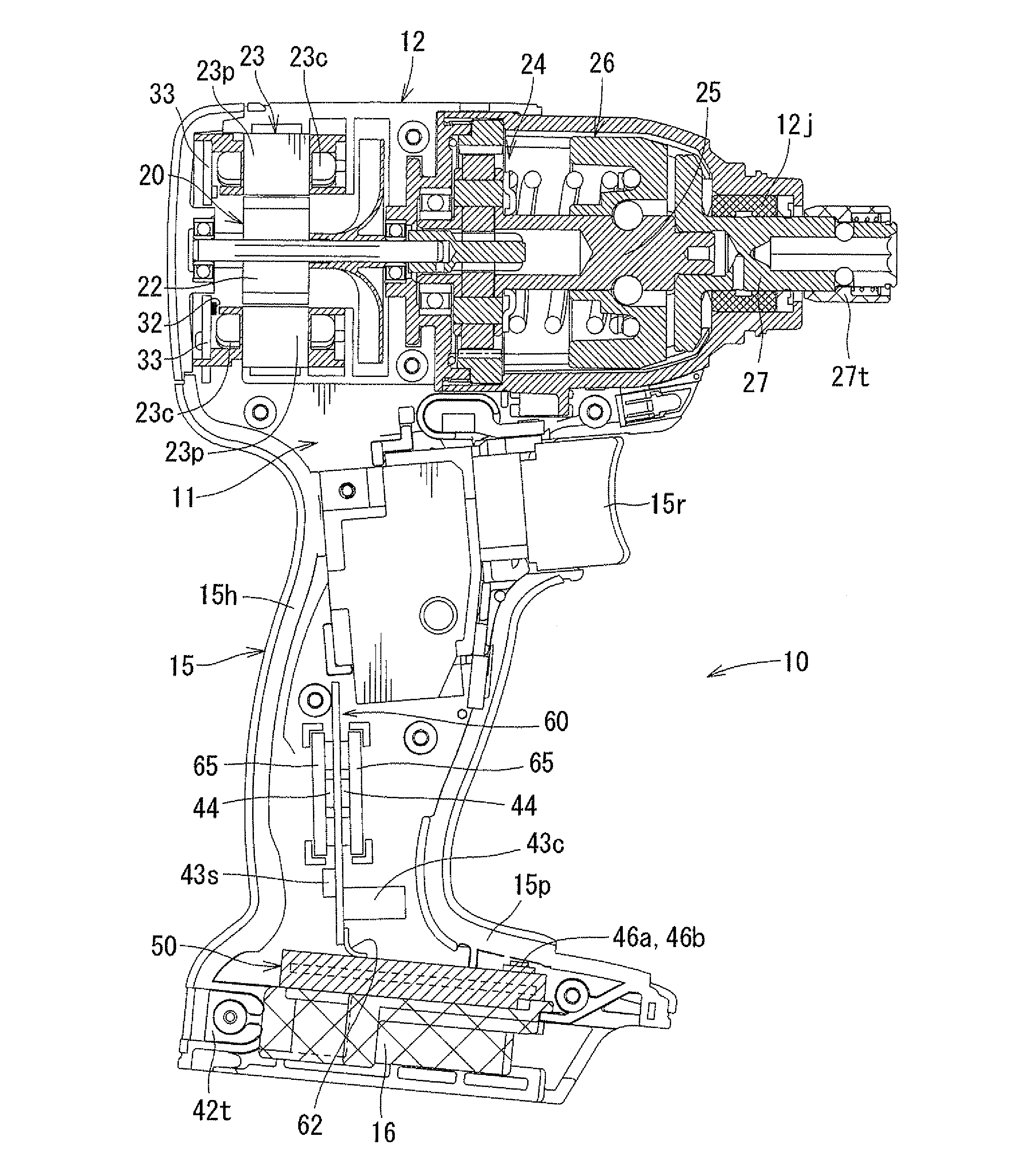
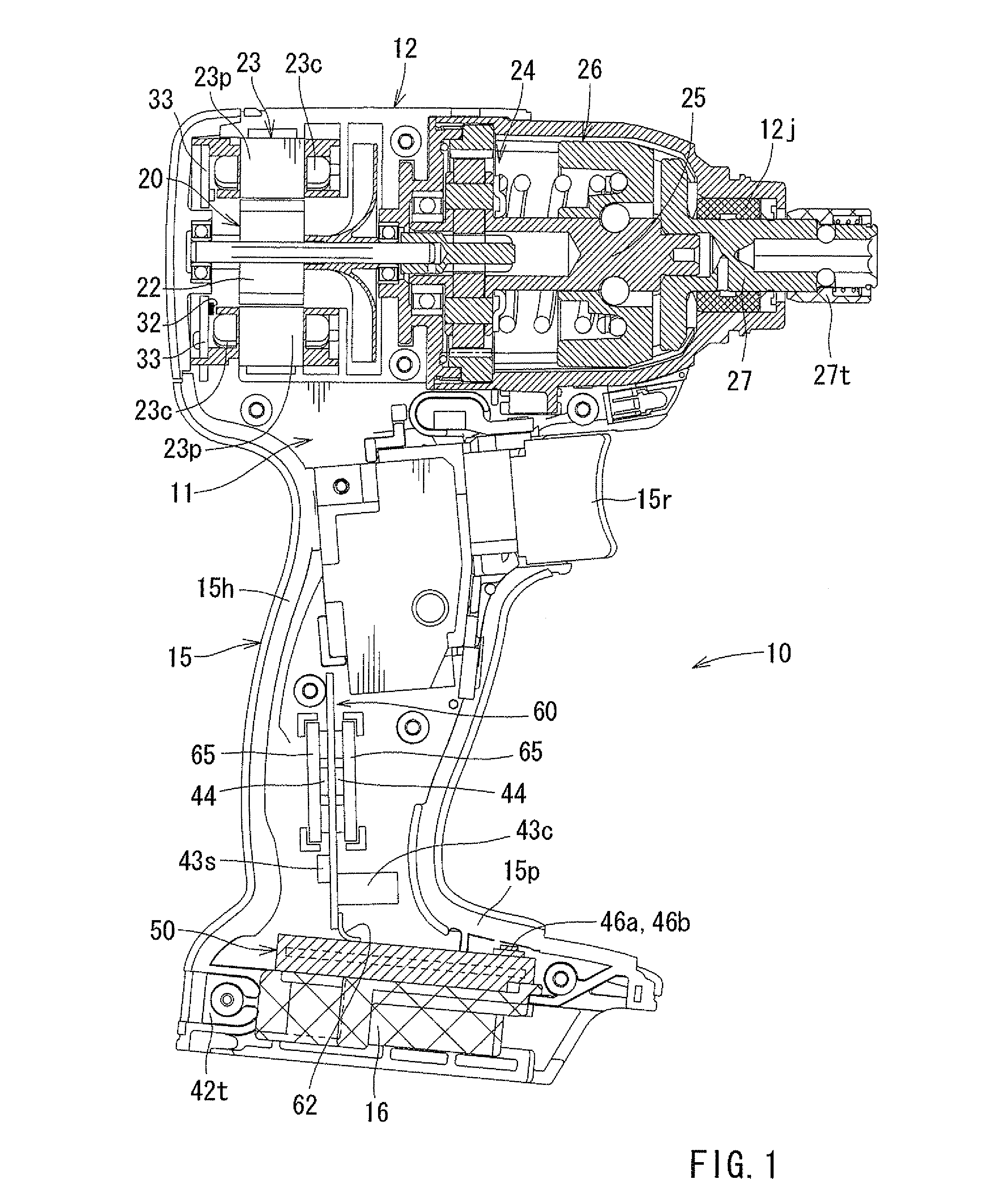
[0023]In the following, an electric power tool according to an embodiment 1 of the present invention will be described with reference to FIGS. 1 to 3. The electric power tool of this embodiment is a rotary driving tool (an impact driver) using a DC brushless motor as the drive source.

[0024]

[0025]As shown in FIG. 1, a housing 11 of an electric power tool 10 according to this embodiment includes a housing main body portion 12, and a grip portion 15 formed to protrude from a side portion (the lower portion as seen in FIG. 1) of the housing main body portion 12. The grip portion 15 includes a handle portion 15h grasped by the user when he or she uses the electric power tool 10, and an exposed portion 15p located on the protruding end (lower end) side of the handle portion 15h. The handle portion 15h is formed in a relatively small diameter so that it can be easily grasped by the user. And, at a proximal end portion of the handle portion 15h, there is provided a trigger type switch lever...

modification examples

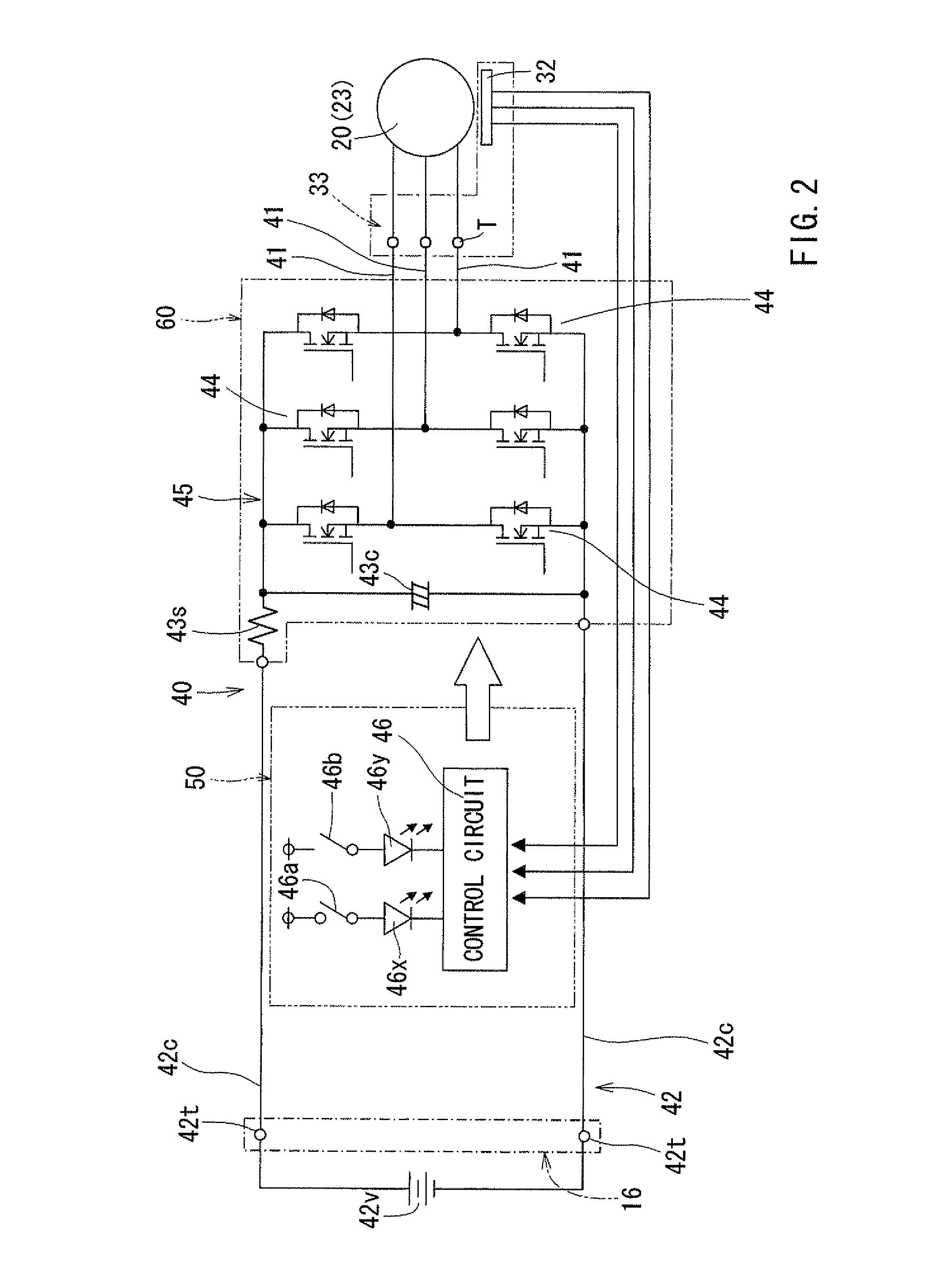
[0054]Here, it should be noted that the present invention is not restricted to the above embodiment but allows modifications without departing from the scope of the invention. For example, in the embodiment described above, the switching elements 44 are covered with the heatsink 65 formed of aluminum alloy, but it is also possible to cover the inner wall surface of the grip portion 15 with a heat insulating material instead of providing the heatsink 65 mentioned above. Further, it is also possible to cover the inner wall surface of the grip portion 15 with a heat insulating material, with the switching elements 44 being covered with the heatsink 65 formed of aluminum alloy. Further, instead of covering them with the heatsink 65, it is also possible to cover the switching elements 44 with a heat insulating material.

[0055]Further, in the embodiment described above, three switching elements 44 are mounted to each of the board front surface and the board rear surface of the power circui...


PUM


Abstract

An electric power tool, which uses a DC brushless motor as a drive source and controls the DC brushless motor by a switching element, can include a tubular housing main body portion accommodating the DC brushless motor, and a grip portion protruding from a side portion of the housing main body portion. The switching element is arranged inside the grip portion, and is spaced apart from an electronic circuit board for an electronic component for operating the switching element.

Description

BACKGROUND OF INVENTION[0001]1. Field of the Invention[0002]The present invention relates to an electric power tool that uses a DC brushless motor as the drive source and controls the DC brushless motor by a switching element.[0003]2. Description of the Related Art[0004]In an electric power tool that controls a DC brushless motor by utilizing a switching element, it is common practice to arrange the switching element behind the DC brushless motor. However, arrangement of the switching element behind the DC brushless motor involves an increase in the entire length of the electric power tool, resulting in deterioration in the usability of the electric power tool.[0005]To solve this problem, Japanese Laid-Open Patent Publication No. 2007-283447 discloses an electric power tool in which a switching element is mounted to an electric circuit board together with an electronic component and is arranged at a protruding end of a grip portion. As a result, there is no need for providing a spac...

Claims


Application Information

Patent Timeline
Patent Type & Authority Patents(United States)
IPC IPC(8): H02K7/14
CPCH02K7/145B25F5/008H02K11/0073H02K11/33
Inventor MATSUNAGA, YUTAKANISHIMIYA, TAKESHI
Owner MAKITA CORP
Why Eureka
Try Eureka