Electric power tool
a technology of electric power tools and electric motors, applied in the direction of dynamo-electric machines, structural associations, control/drive circuits, etc., can solve problems such as deterioration in the usability of electric power tools, and achieve the effect of increasing the length of electric power tools and reducing heat protection measures
- Summary
- Abstract
- Description
- Claims
- Application Information
AI Technical Summary
Benefits of technology
Problems solved by technology
Method used
Image

Examples
embodiment 1
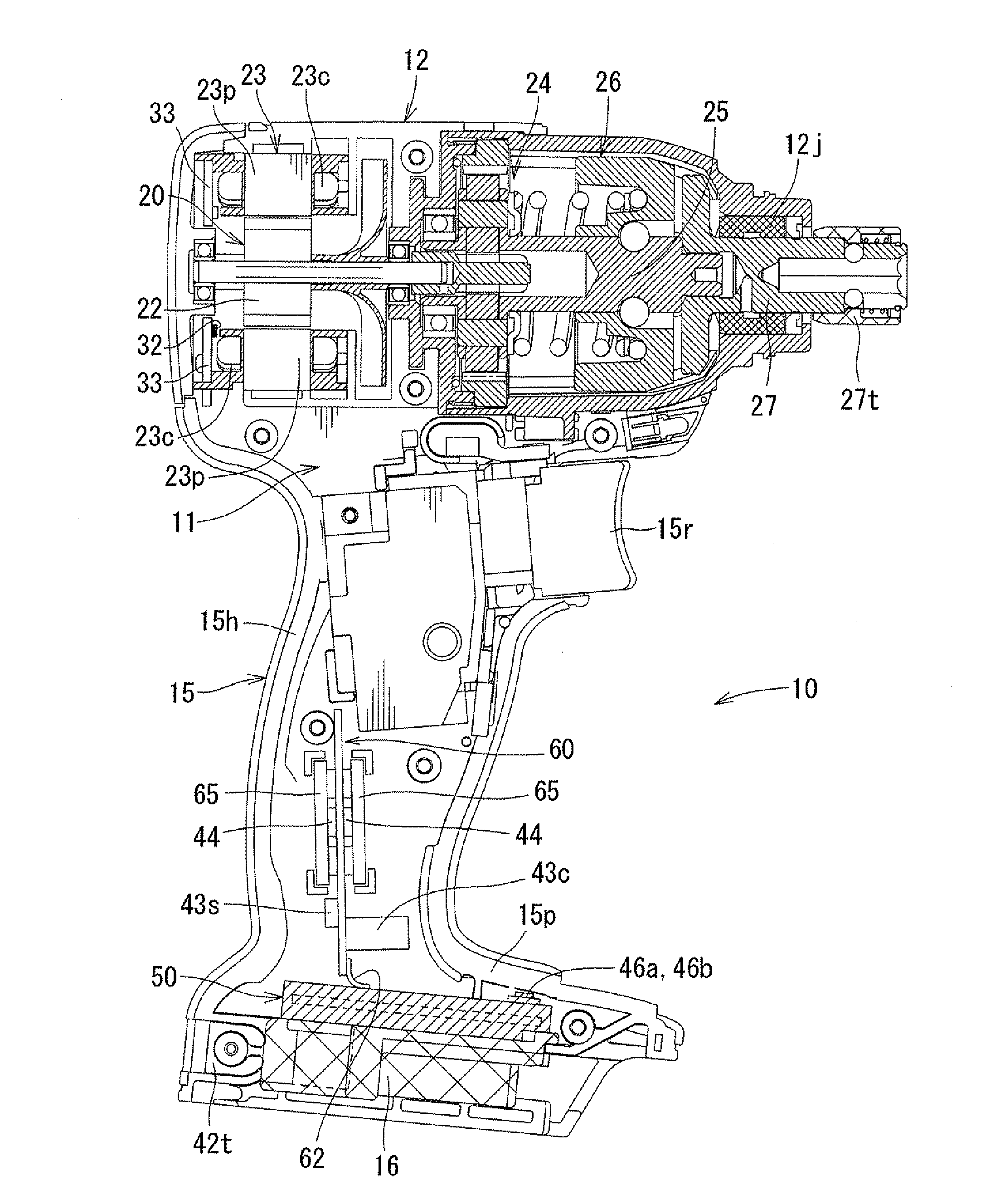
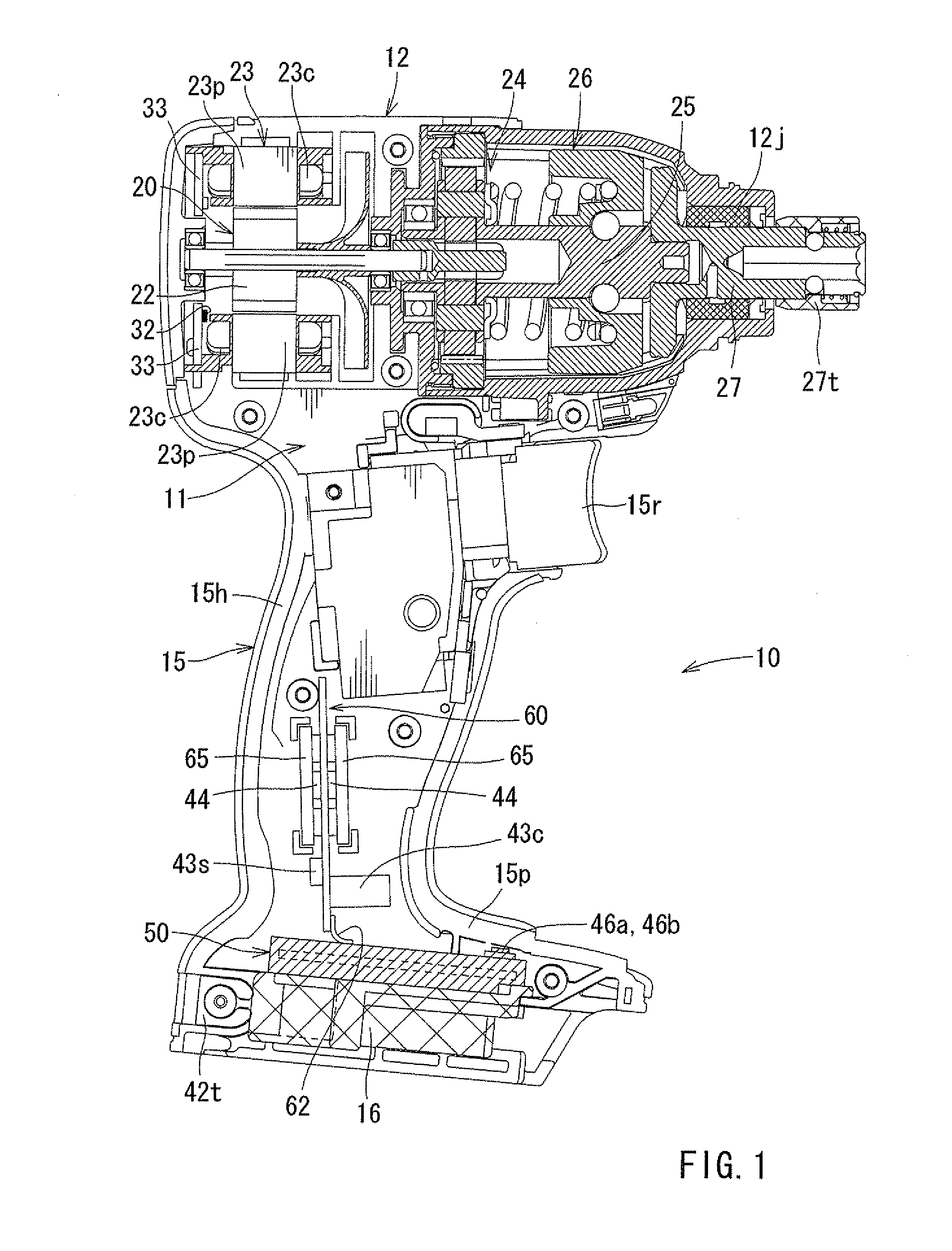
[0023]In the following, an electric power tool according to an embodiment 1 of the present invention will be described with reference to FIGS. 1 to 3. The electric power tool of this embodiment is a rotary driving tool (an impact driver) using a DC brushless motor as the drive source.
[0024]
[0025]As shown in FIG. 1, a housing 11 of an electric power tool 10 according to this embodiment includes a housing main body portion 12, and a grip portion 15 formed to protrude from a side portion (the lower portion as seen in FIG. 1) of the housing main body portion 12. The grip portion 15 includes a handle portion 15h grasped by the user when he or she uses the electric power tool 10, and an exposed portion 15p located on the protruding end (lower end) side of the handle portion 15h. The handle portion 15h is formed in a relatively small diameter so that it can be easily grasped by the user. And, at a proximal end portion of the handle portion 15h, there is provided a trigger type switch lever...
modification examples
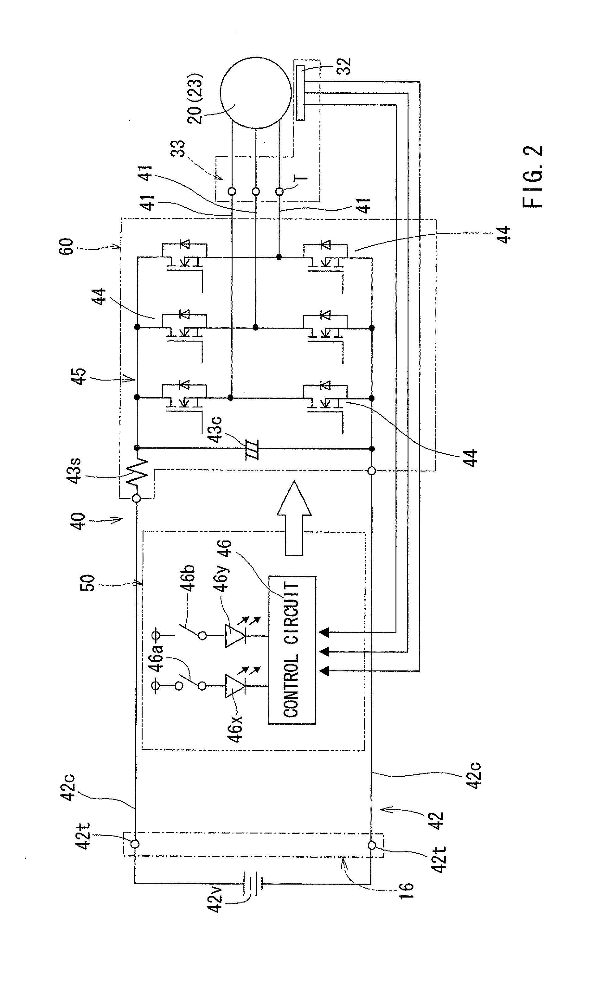
[0054]Here, it should be noted that the present invention is not restricted to the above embodiment but allows modifications without departing from the scope of the invention. For example, in the embodiment described above, the switching elements 44 are covered with the heatsink 65 formed of aluminum alloy, but it is also possible to cover the inner wall surface of the grip portion 15 with a heat insulating material instead of providing the heatsink 65 mentioned above. Further, it is also possible to cover the inner wall surface of the grip portion 15 with a heat insulating material, with the switching elements 44 being covered with the heatsink 65 formed of aluminum alloy. Further, instead of covering them with the heatsink 65, it is also possible to cover the switching elements 44 with a heat insulating material.
[0055]Further, in the embodiment described above, three switching elements 44 are mounted to each of the board front surface and the board rear surface of the power circui...
PUM
 Abstract
Description
Claims
Application Information
 - R&D
- Intellectual Property
- Life Sciences
- Materials
- Tech Scout
- Unparalleled Data Quality
- Higher Quality Content
- 60% Fewer Hallucinations
Browse by: Latest US Patents, China's latest patents, Technical Efficacy Thesaurus, Application Domain, Technology Topic, Popular Technical Reports.
© 2025 PatSnap. All rights reserved.Legal|Privacy policy|Modern Slavery Act Transparency Statement|Sitemap|About US| Contact US: help@patsnap.com