Auxiliary device for binding reinforcements of reinforced concrete beam and application thereof

A technology of reinforced concrete beams and auxiliary devices, which is applied in the processing of building materials, construction, building structure, etc., can solve the problems of safety, low reliability, inconvenient operation, instability, etc., and achieve high social and economic benefits. , Reduce the waste of resources, the effect of stable and reliable force

Inactive Publication Date: 2013-03-20
SHANGHAI ZHONGJIN CONSTR GRP
View PDF9 Cites 14 Cited by
  • Summary
  • Abstract
  • Description
  • Claims
  • Application Information

AI Technical Summary

Problems solved by technology

These support measures generally have problems such as inconvenient operation, inability to adjust the height, and the need to re-build beams of different heights.
In addition, the support frame is built based on experience, and the bearing capacity has not been strictly checked, and instability occurs from time to time
[0004] After searching the existing literature, it was found that in the patent "A Reusable Reinforcement Cage Lifting Device" applied by Shu An et al. in 2011, a device that can adjust the height of the bracket is disclosed, which is used to bind steel bars of different beam heights. , but its force is entirely carried by the thread, and its safety and reliability are low

Method used


Image

  • Auxiliary device for binding reinforcements of reinforced concrete beam and application thereof
  • Auxiliary device for binding reinforcements of reinforced concrete beam and application thereof
  • Auxiliary device for binding reinforcements of reinforced concrete beam and application thereof

Examples


Embodiment 1

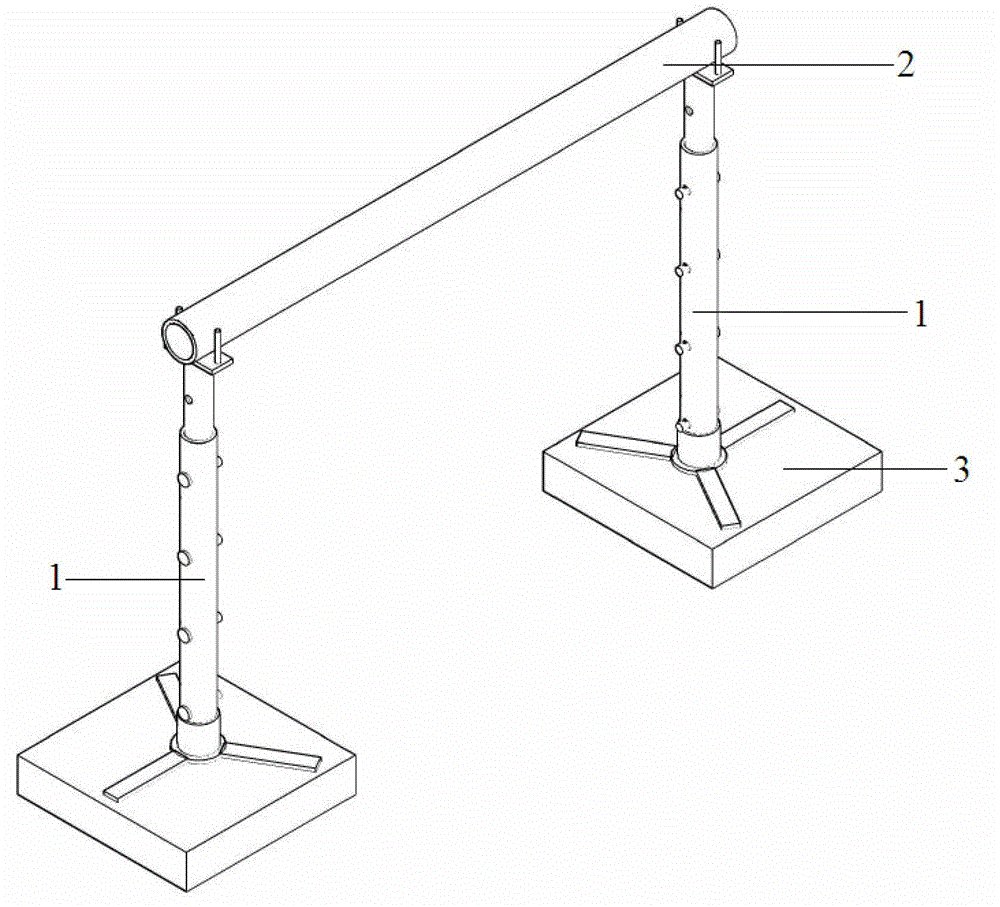
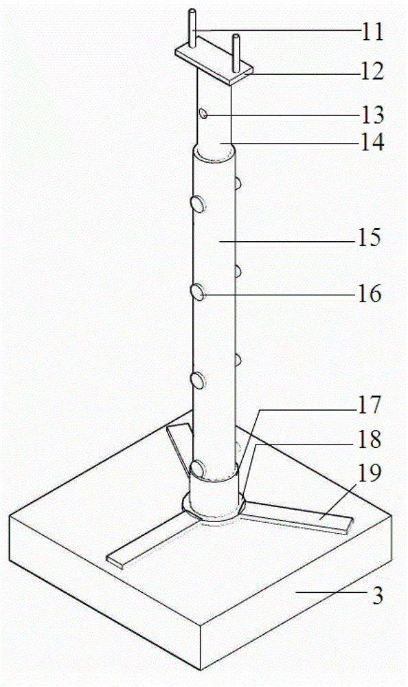
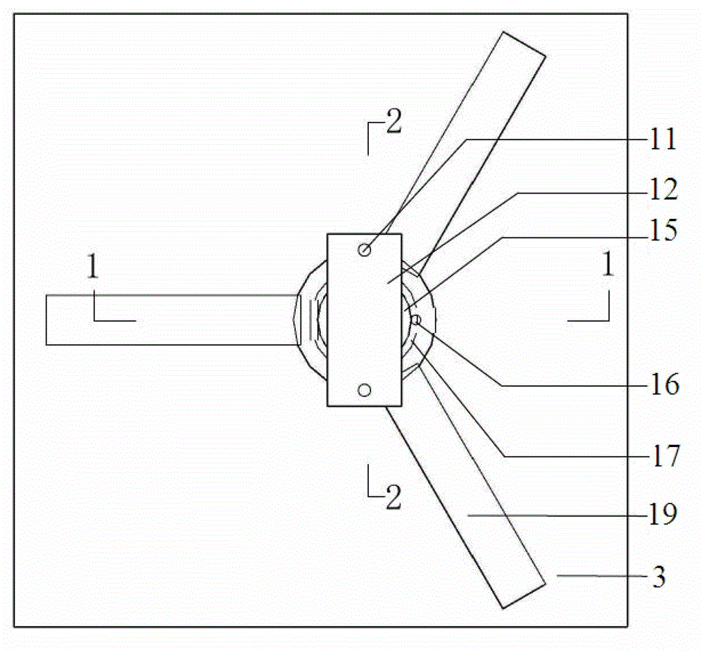
[0037] An auxiliary device for binding steel bars of reinforced concrete beams, the structure of which is as Figure 1 to Figure 5 As shown, the auxiliary device includes two brackets 1 arranged side by side and a cross bar 2 overlapped on the two brackets 1 , and the bracket 1 is a telescopic bracket 1 . The bracket 1 includes an inner tube 14 and an outer tube 15, the inner tube 14 is inserted into the outer tube 15 and is telescopically connected with it, the lower end of the outer tube 15 is provided with a fixing piece, the upper end of the inner tube 14 is provided with a joint base, and a cross bar 2 lapped on the docking base. Both the inner tube 14 and the outer tube 15 are provided with a plurality of through holes 13 along the length thereof, and the specifications and positions of the through holes 13 of the inner tube 14 are consistent with those of the outer tube 15 . The inner tube 14 is connected to the outer tube 15 by inserting the pin 16 into the through ho...

Embodiment 2

[0047] An auxiliary device for binding steel bars of reinforced concrete beams, the structure of which is as Figure 1 to Figure 5 As shown, the auxiliary device includes two brackets 1 arranged side by side and a cross bar 2 overlapped on the two brackets 1 , and the bracket 1 is a telescopic bracket 1 . The bracket 1 includes an inner tube 14 and an outer tube 15, the inner tube 14 is inserted into the outer tube 15 and is telescopically connected with it, the lower end of the outer tube 15 is provided with a fixing piece, the upper end of the inner tube 14 is provided with a joint base, and a cross bar 2 lapped on the docking base. Both the inner tube 14 and the outer tube 15 are provided with a plurality of through holes 13 along the length thereof, and the specifications and positions of the through holes 13 of the inner tube 14 are consistent with those of the outer tube 15 . The inner tube 14 is connected to the outer tube 15 by inserting the pin 16 into the through hole...

Embodiment 3

[0057] An auxiliary device for binding steel bars of reinforced concrete beams, the structure of which is as Figure 1 to Figure 5 As shown, the auxiliary device includes two brackets 1 arranged side by side and a cross bar 2 overlapped on the two brackets 1 , and the bracket 1 is a telescopic bracket 1 . The bracket 1 includes an inner tube 14 and an outer tube 15, the inner tube 14 is inserted into the outer tube 15 and is telescopically connected with it, the lower end of the outer tube 15 is provided with a fixing piece, the upper end of the inner tube 14 is provided with a joint base, and a cross bar 2 lapped on the docking base. Both the inner tube 14 and the outer tube 15 are provided with a plurality of through holes 13 along the length thereof, and the specifications and positions of the through holes 13 of the inner tube 14 are consistent with those of the outer tube 15 . The inner tube 14 is connected to the outer tube 15 by inserting the pin 16 into the through ho...


PUM


Abstract

The invention relates to an auxiliary device for binding reinforcements of a reinforced concrete beam and application thereof. The device comprises two telescopic brackets and a cross bar, wherein the two telescopic brackets are arranged in parallel; and the cross bar is overlapped on the two brackets. The application of the auxiliary device is as follows: according to the condition of the beam depth, the heights of the brackets are regulated, so that the brackets are slightly higher than the beam; the auxiliary devices are arranged in pairs along the beam length direction at intervals of 3 to 5m and the auxiliary devices are placed on plate formworks at both sides of a beam formwork; beam upper main reinforcements are placed on the cross bars, beam stirrups are sleeved, beam lower main reinforcements are inserted and the reinforcements are bound to form a beam reinforcement skeleton; the beam reinforcement skeleton is pulled up, the auxiliary devices at the end where the reinforcement binding is completed are removed, the beam reinforcement skeleton is slowly placed into the beam formwork; and the pair of auxiliary devices at the upper part are moved to a next section to bind reinforcements of the section of beam. Compared with the prior art, the device disclosed by the invention is stably stressed, is convenient to use, has an adjustable height, can be reused, can be suitable for binding reinforcements with different beam depths, can be industrially produced in batches and has high social benefits and economic benefits.

Description

technical field [0001] The invention relates to an auxiliary device for building construction, in particular to an auxiliary device for binding steel bars of reinforced concrete beams and its application. Background technique [0002] In the construction process of reinforced concrete structures, the initial construction process of binding the steel bars in the beam is: supporting the beam bottom formwork→binding the beam internal steel bars→supporting the beam side formwork and slab formwork. This kind of construction technology has problems such as multi-step interleaving, low work efficiency, high-altitude operation, and inconvenient walking. In particular, the steel skeleton in the bound beam is easily trampled and deformed. [0003] In order to solve the above problems, the engineering field has improved the construction process, that is, the bottom formwork, side formwork and slab formwork of the beam are supported first, and the beam "groove" is formed at the design p...

Claims


Application Information

Patent Timeline
Patent Type & Authority Applications(China)
IPC IPC(8): E04G21/12
Inventor 秦浩丁继业李军
Owner SHANGHAI ZHONGJIN CONSTR GRP
Why Eureka
Try Eureka