
High pressure compressed air regulating valve

A technology of compressing air and regulating valves, applied in the direction of valve details, safety valves, balance valves, etc., to achieve the effect of overcoming destructive forces

Inactive Publication Date: 2013-03-20
NANJING HUANING VALVE
View PDF7 Cites 2 Cited by
  • Summary
  • Abstract
  • Description
  • Claims
  • Application Information

AI Technical Summary

Problems solved by technology

[0003] The invention provides a high-pressure compressed air regulating valve for reducing destructive force, noise, chatter and leakage

Method used


Image

  • High pressure compressed air regulating valve
  • High pressure compressed air regulating valve
  • High pressure compressed air regulating valve

Examples


Embodiment Construction

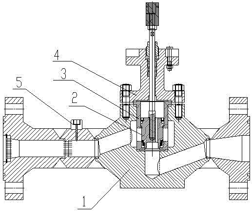
[0012] Below in conjunction with accompanying drawing, the present invention is described in further detail:

[0013] As shown in the figure: a high-pressure compressed air regulating valve, including a valve body 1, a balanced disc assembly 2, a valve cage 3, and a valve cover assembly 4.

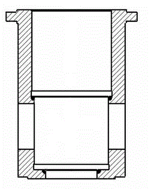
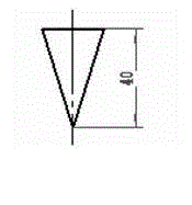
[0014] The valve cover assembly 4 is arranged on the upper end of the valve body 1, and the valve cage 3 is arranged inside the valve body 1. The balanced disc assembly 2 is arranged on the valve cage 3 and extends out of the valve cover assembly 4. The window of the valve cage 3 is V-shaped. window.

[0015] The balanced disc assembly 2 relies on the interference fit between the upper and lower sealing rings (polymer material) and the V-shaped window cage 3 to ensure that all media enter the outlet after being adjusted through the V-shaped window, and the upper and lower cone surfaces of the disc The sealing surface (tungsten carbide material) and the tapered sealing surface (tungsten ca...


PUM


Abstract

The invention relates to a valve, in particular to a valve for regulating flow of high pressure compressed air. The valve comprises a balanced valve clack combined piece, a valve cage and a valve cap component, wherein the valve cap component is placed at the upper end of the valve body; the valve cage is placed in the valve body; the balanced valve clack combined piece is placed in the valve cage and extends out of the valve cap component; and a window of the valve cage is a V-shaped window. In the high pressure compressed air regulating valve provided by the invention, through the adoption of a group of regular circular holes in a fixed flow limiting pore plate, the pressure of the compressed air can be effectively attenuated and a rectifying effect can be obtained; and on the basis of the effect of the fixed flow limiting pore plate, a replaceable flow limiting pore plate can be replaced according to the actual need of a pressure regulating range and according to a value indicated on a pressure gauge in a pressure port. The invariability of flow characteristic of a common regulating valve is overcome.

Description

technical field [0001] The invention relates to a valve, in particular to a valve for regulating the flow of high-pressure compressed air. Background technique [0002] Aircraft wind tunnel test sites and sites that use compressed air as the power source require precise adjustments to the flow rate of high-pressure compressed air. The flow rate changes frequently, and the range of pressure and flow rate changes is large, and zero leakage is required in the closed state. This product was developed to overcome the destructive force, noise, chatter, and leakage caused by this special working condition, and to meet the ability to adjust the flow rate linearly under this working condition. Contents of the invention [0003] The invention provides a high-pressure compressed air regulating valve aiming at reducing destructive force, noise, vibration and leakage. [0004] The present invention adopts following technical scheme: [0005] A high-pressure compressed air regulating ...

Claims


Application Information

Patent Timeline
Patent Type & Authority Applications(China)
IPC IPC(8): F16K17/20F16K47/02
Inventor 张家清王勇
Owner NANJING HUANING VALVE
Learn More