I/O hole detecting machine platform

A technology of machine and detection device, which is applied in measurement devices, instruments, and optical devices, etc., can solve problems such as lower detection efficiency

Active Publication Date: 2013-03-20
SUZHOU RS TECH
View PDF7 Cites 5 Cited by
  • Summary
  • Abstract
  • Description
  • Claims
  • Application Information

AI Technical Summary

Problems solved by technology

But for slender holes, if it is detected whether it is blocked by impurities or not opened, it is necessary to manually detect or calculate the permeability of the hole through the program according to the image, and the permeability is the actual through hole area and The ratio of the theoretical through-hole area, the detection efficiency is greatly reduced by the above method

Method used


Image

  • I/O hole detecting machine platform
  • I/O hole detecting machine platform
  • I/O hole detecting machine platform

Examples


Embodiment Construction

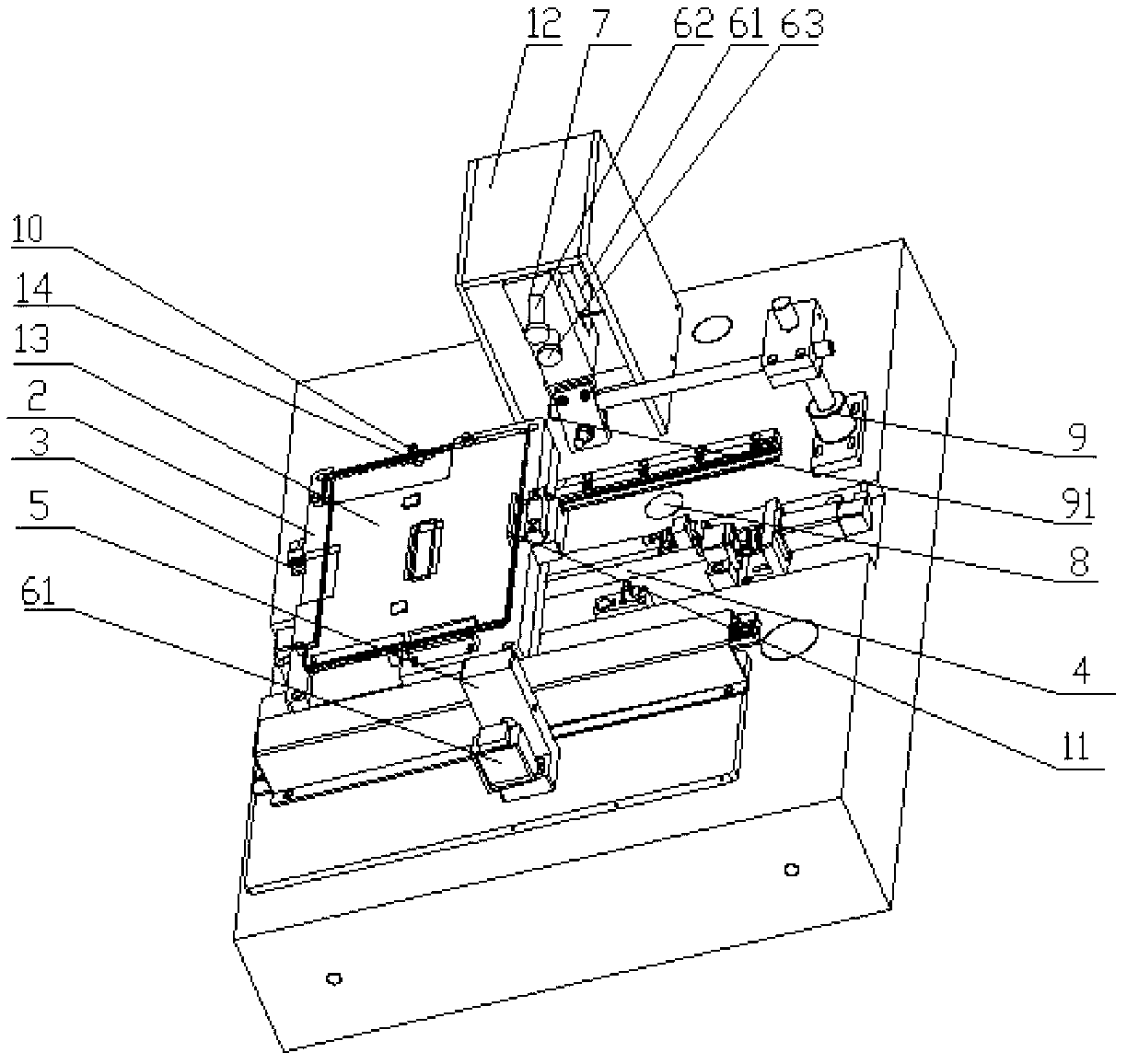
[0019] figure 1 The shown I / O hole detection machine includes a base 1, a workbench 2, a guide rail 3, a screw 41, a movable nut 42, an L-shaped support 5, a CCD imaging device 61, a lens 62, a light source 63, and a positioning hole 7. Active light source 8, support 9, light source 91, positioning pin 10, pressing device 11, protective cover 12, product 13 and reference hole 14.

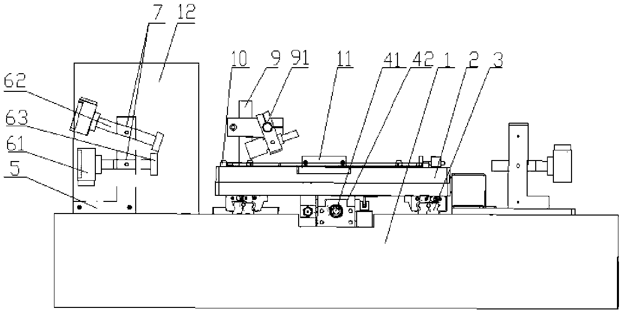
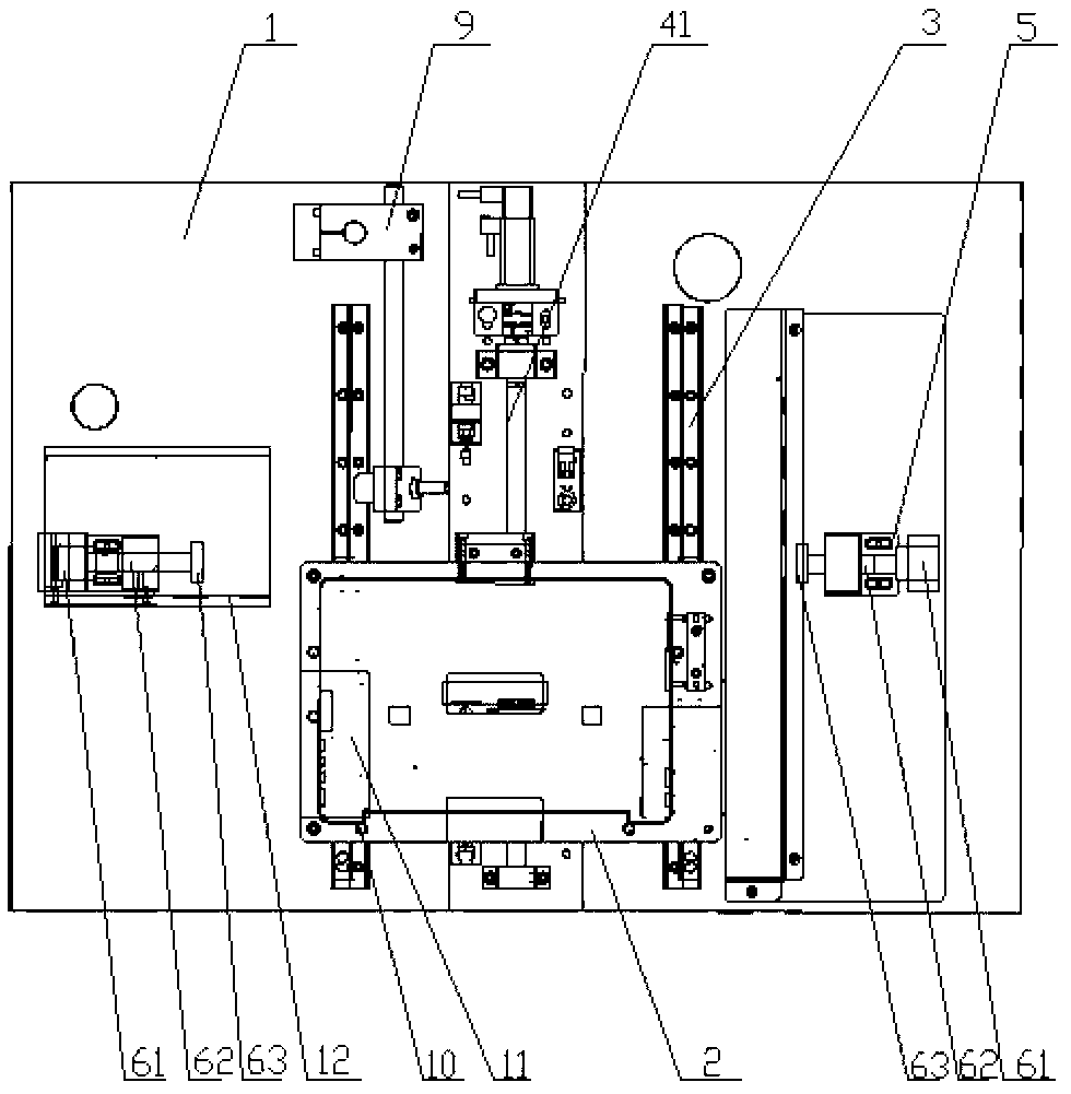
[0020] figure 2 , image 3 with Figure 4 The shown I / O hole detection machine mainly includes a base 1, a workbench 2, a screw 41 and related linkage structures and detection devices. The workbench 2 is placed on the base 1 through a screw mechanism, and the lead screw 41 and The related linkage mechanism consists of two guide rails 3 arranged in parallel on the base, a lead screw 41, a motor, a control program, and a movable nut 42 fixedly connected to the workbench. The relative position of the table. The two detection devices are arranged on the same straight line outside the two parallel ...


PUM


Abstract

The invention discloses an I / O hole detecting machine platform mainly comprising a base and a working platform. The working platform is arranged on the base, guiding rails and a lead screw mechanism are arranged between the base and working platform. A motor is connected with the tail end of a lead screw, and the controlling end of the motor is connected with the signal feedback end of a controlling program. The I / O detecting machine platform is characterized in that L-shaped supporting bases are both arranged on the outer sides of the two guiding rails on the base and perpendicular to the extending direction of the guiding rails. Detecting devices on the L-shaped supporting bases comprise charge coupled device (CCD) imaging devices, camera lenses and light sources. The camera lenses penetrate positioning holes on the side edges of the L-shaped supporting bases. The two ends of each camera lens are respectively connected with one CCD imaging device and one light source. A zero degree is formed between the center axis of one camera lens and a level surface, wherein in the other arranged detecting device arranged on one L-shaped supporting base at one side, an included angle is formed between a center axis of the camera lens and the level surface and in range from zero degree to 45 degrees. By utilizing the CCD imaging devices, sizes and location degrees of holes to be detected in products are obtained, status of profile tolerance of square-shaped holes in the products is obtained, pass-through rate of the holes to be detected are obtained and the holes are checked to be got through or blocked by impurities.

Description

technical field [0001] The invention relates to an I / O hole detection machine, in particular to an accurate and efficient I / O hole detection machine. Background technique [0002] Due to the needs of external interfaces on the housing of electronic products, according to the design requirements, there are usually a number of holes for the passage of external devices on the housing. In order to ensure its quality, it is usually necessary to detect the size and position of the holes, as well as the contour of the corresponding square holes. . In order to realize automatic detection, the combination of CCD imaging technology and control program is usually used to issue action instructions through the control program to control the product to be inspected to move to the corresponding position, use CCD technology to affect the part of the scene to be inspected, and use software to process data for the viewfinder image. In this way, the pixels of the learned part are obtained, an...

Claims


Application Information

Patent Timeline
Patent Type & Authority Applications(China)
IPC IPC(8): G01B11/00G01B11/24
Inventor 缪磊任锋吴加福
Owner SUZHOU RS TECH
Why Eureka
Try Eureka