Non-destructive testing system and method for special welding of steel structure

A non-destructive testing and steel structure technology, which is applied in the direction of optical testing of flaws/defects, using sound waves/ultrasonic waves/infrasonic waves to analyze solids, etc., can solve the problems of time-consuming and labor-intensive detection and identification, low detection efficiency, and low recognition accuracy. Accuracy and measurement efficiency, high real-time performance, and high measurement accuracy

Active Publication Date: 2016-07-06
SHANGHAI JIAOTONG UNIV
View PDF6 Cites 0 Cited by
  • Summary
  • Abstract
  • Description
  • Claims
  • Application Information

AI Technical Summary

Problems solved by technology

[0004] The purpose of the present invention is to provide a non-destructive testing system for special welding of steel structures to solve the technical problems of time-consuming and labor-intensive detection and recognition in the existing ultrasonic steel structure internal defect detection methods, low recognition accuracy, poor accuracy and low detection efficiency
[0005] Another object of the present invention is to provide a non-destructive testing method for special welding of steel structures, so as to solve the technical problems of existing ultrasonic steel structure internal defect detection methods that are time-consuming and labor-intensive for detection and identification, low recognition accuracy, poor accuracy, and low detection efficiency.

Method used


Image

  • Non-destructive testing system and method for special welding of steel structure
  • Non-destructive testing system and method for special welding of steel structure

Examples


Embodiment Construction

[0027] The present invention will be described in detail below in conjunction with the accompanying drawings.

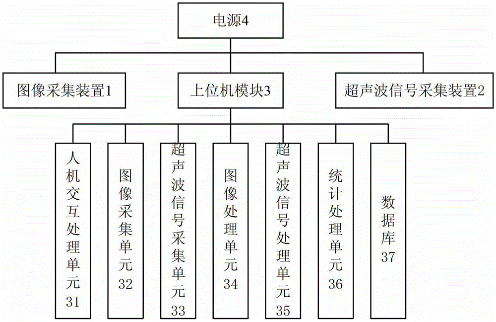
[0028] see figure 1 , a non-destructive testing system for special welding of steel structures, comprising: an image acquisition device 1, an ultrasonic signal acquisition device 2, a host computer module 3 and a power supply 4, the image acquisition device 1 adopts a CMOS color camera, which is connected with the host computer module 3, and used To collect the weld seam image of the steel structure in real time and send it to the upper computer module 3; the ultrasonic signal acquisition device 2 is connected to the upper computer module 3 to collect ultrasonic signals and generate ultrasonic waveform diagrams for analysis, and the upper computer module 3 is used to collect Analyze the received image and ultrasonic waveform, locate the weld defect and analyze the weld defect situation, and obtain specific defect information and defect parameters; the power supply 4 ...


PUM


Abstract

Disclosed are a system and a method of nondestructive testing of steel structure special type weld. The system of the nondestructive testing of the steel structure special type weld comprises an image collecting device, an ultrasonic signal collecting device, an upper monitor module and a power source. The image collecting device is connected with the upper monitor module and is used for collecting a steel structure weld joint image at real time and then the steel structure weld joint image is sent to the upper monitor. The ultrasonic signal collecting device is connected with the upper monitor module and is used for collecting an ultrasonic signal and generating an ultrasonic wave form image used for analysis. The upper monitor is used for analyzing the collected image and the collected ultrasonic wave form,and locating a weld joint defect,and analyzing the weld joint defect situation, and then obtains defect particular information and defect parameter. The image collecting device and the ultrasonic signal collecting device are respectively connected with the power source, and the upper monitor module and is used for supplying power to the image collecting device and the ultrasonic signal collecting device and the upper monitor module. The system and the method of the nondestructive testing of the steel structure special type weld have the advantages of being easy to operate, high in measurement precision and accuracy, high in work efficiency, convenient and easy to use and high in real-time property.

Description

technical field [0001] The invention relates to the field of steel structure detection, in particular to a nondestructive detection system and method for special welding of steel structures. Background technique [0002] Steel structure welding is a relatively special physical metallurgical process. There are many reasons that can affect the welding quality of welded components, such as the defects of the welding process, the problems of the equipment itself, the influence of materials and other factors, which will bring disadvantages to the mechanical properties of the steel structure. influences. The principle of non-destructive testing technology used in steel structure welding is to detect the quality of the welding without affecting the performance of the steel structure, and to identify the defects by changing the parameters of light, magnetic field and vibration caused by welding defects . [0003] At present, the commonly used detection methods for internal defects...

Claims


Application Information

Patent Timeline
Patent Type & Authority Patents(China)
IPC IPC(8): G01N21/88G01N29/04
Inventor 胡洁黄海清戚进谷朝臣刘超
Owner SHANGHAI JIAOTONG UNIV
Why Eureka
Try Eureka