

Coarse-pitch one-dimensional vertical lifting adjustment rack
A technology of vertical lifting and large pitch, applied in installation, optics, instruments, etc., can solve the problems affecting the working mood of experimenters, difficulties in optical path arrangement, optical components swing, etc., to achieve convenient assembly and operation, accurate vertical lifting, and convenient use Effect
Patent Information
- Authority / Receiving Office
- CN · China
- Patent Type
- Applications(China)
- Current Assignee / Owner
- Publication Date
- 2013-03-20
- Estimated Expiration
- Not applicable · inactive patent
Smart Images
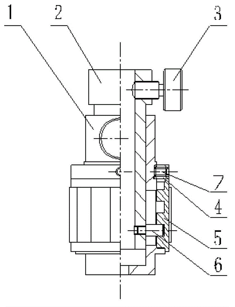
Figure 1 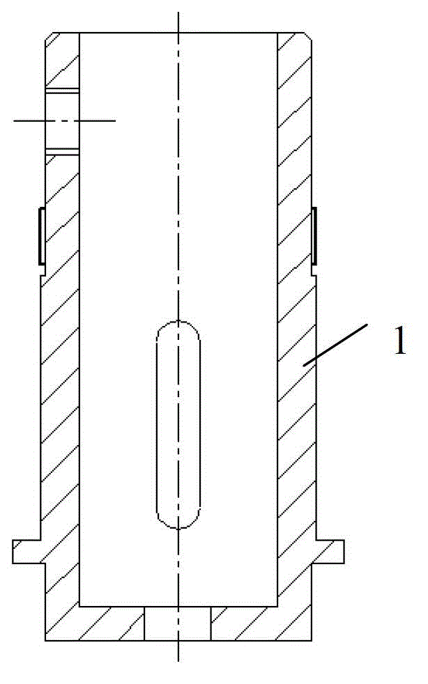
Figure 2 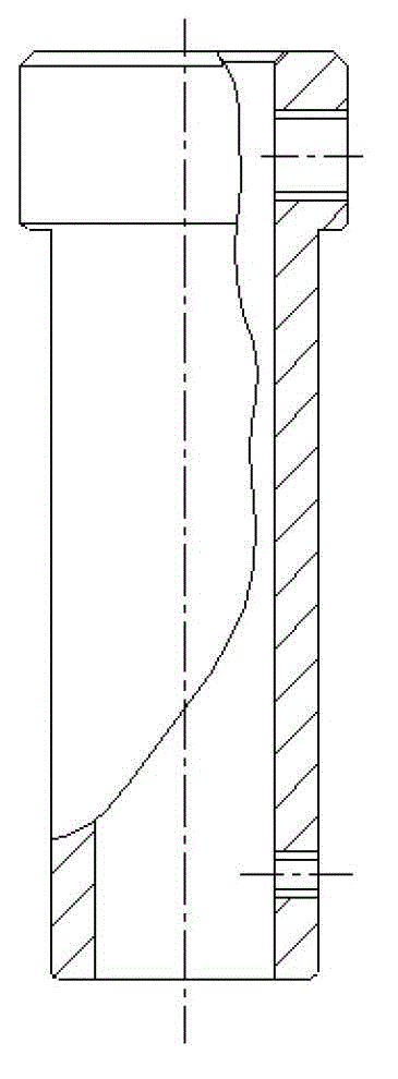
Figure 3
Abstract
Description
technical field
[0001] The invention relates to a vertical lifting adjustment mechanism in optical light path experiments, in particular to a large-pitch vertical lifting one-dimensional adjusting frame which does not deflect the axis during the adjustment and lifting process. Background technique
[0002] When studying the optical path arrangement of optical characteristics, it is a common requirement to adjust the optical components up and down. However, when the existing adjustment means are adjusted, the optical elements often have adjustment instability such as swinging and axial deflection, which makes it difficult to arrange the optical path and the adjustment is cumbersome. Due to these reasons, a lot of time is consumed only in the process of vertical adjustment of optical elements, resulting in low experimental efficiency and affecting the working mood of experimenters. Contents of the invention
[0003] In order to solve the above-mentioned technical problems, ...
Examples
Embodiment Construction
[0017] The structure of the large-pitch vertical lifting one-dimensional adjusting frame of the present invention will be described below in conjunction with the accompanying drawings.
[0018] like figure 1 As shown, the large-pitch vertical lifting one-dimensional adjustment frame of the present invention includes a fixed sleeve 1, a sliding shaft 2, a screw 3, a pressure sleeve 4, a threaded sleeve 5, and a slider 6.
[0019] The sliding shaft 2 is inserted into the shaft hole of the fixed sleeve 1 and can slide, one end of the slider 6 passes through the guide groove of the fixed sleeve 1 and is fastened on the sliding shaft 2, and the other end of the slider 6 is inserted into the spiral groove in the threaded sleeve 5 , when rotating, the thread groove drives the slider 6 up and down, and drives the sliding shaft 2 to slide up and down, and the upper end of the threaded sleeve 5 is provided with a pressure sleeve 4, which is fixed on the fixed sleeve 1 by a set screw 7, ...