
Model correcting method based on defective modal structure

A defect modal and structural model technology, applied in special data processing applications, instruments, electrical digital data processing, etc., can solve the problem that no one has proposed, does not consider the information of measurement eigenvectors, and cannot guarantee positive definiteness or semi-positive definiteness, etc. problems, to avoid errors and improve accuracy

Active Publication Date: 2013-03-20
THE 28TH RES INST OF CHINA ELECTRONICS TECH GROUP CORP
View PDF2 Cites 12 Cited by
  • Summary
  • Abstract
  • Description
  • Claims
  • Application Information

AI Technical Summary

Problems solved by technology

The usual correction method can only guarantee the symmetry of the corrected model, and generally cannot guarantee the positive definiteness or semi-positive definiteness, thus making the model lose its physical meaning
③ Degree of freedom of measurement data is incomplete
Carvalho et al. (5. Carvalho J, Datta B N, LinW W, et al. Symmetry preserving eigenvalue embedding in finite-element model updating of vibrating structures. Journal of Sound and Vibration, 2006, 290(3-5): 839~864) proposed The eigenvalue embedding technology not only ensures the symmetry of the modified model, but also makes the remaining modal data of the modified model consistent with the original model (no overflow). The disadvantage is that the information of the measured eige

Method used


Image

  • Model correcting method based on defective modal structure
  • Model correcting method based on defective modal structure
  • Model correcting method based on defective modal structure

Examples


Embodiment Construction

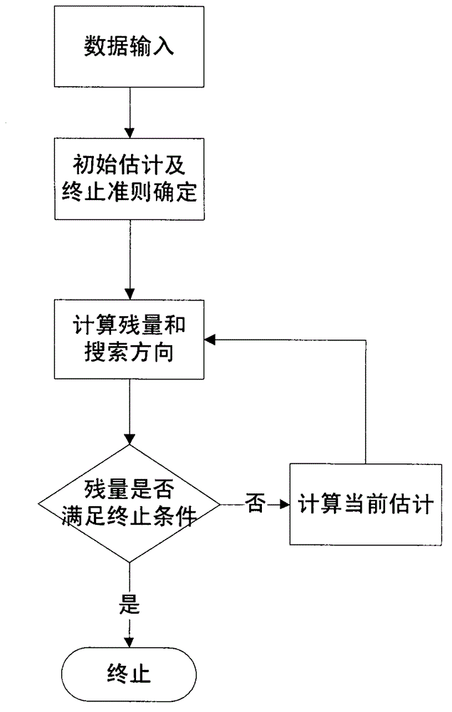
[0018] combine figure 1 , a structural model correction method based on defect modes, the steps are as follows:

[0019] Step 1. Format the initial data, that is, separate the measured degrees of freedom from the unmeasured degrees of freedom in the modal data by adjusting the number of degrees of freedom, and convert the complex modal data to real numbers, so as to ensure that all operations are carried out in real time. execute in form; combine figure 2 , the specific steps to format the initial data are:

[0020] Step 1-1. Set all degrees of freedom as {1, 2, ... N}, {m 1 , m 2 ,...m l} are l measured degrees of freedom, and the remaining unmeasured degrees of freedom are denoted as {m l+1 ,...m N};

[0021] Step 1-2, separate the measured degrees of freedom from the unmeasured degrees of freedom to obtain the permutation matrix P(m 1 , m 2 ,...m l , m l+1 ,...m N ), where P(m 1 , m 2 ,...m l , m 1+1 ,...m N ) by all column vectors of the N-order identity ...


PUM


Abstract

The invention discloses a model correcting method based on a defective modal structure. The model correcting method first formats initial data, and the initial data of a required format is obtained through an adjustment of freedom degree numbers and a real number conversion of a complex mode. The extension of defective modal data is achieved by conducting matrix QR decomposition on model data to be corrected after the formatting of the initial data, obtaining a matrix equation of the defective modal data and utilizing least square method to solve the matrix equation. The confirming of corrected parameters is achieved by building a matrix equation of corrected parameters through extended modal data and utilizing a structure preserving iterative algorithm to solve the matrix equation. The corrected model is a finite element model calculated and corrected by the corrected parameters which are obtained through the structure preserving iterative algorithm and non-overflowing revising format. The model correcting method based on the defective modal structure can not only deal with the difficulty that the freedom degree of the modal data is not complete in actual measurement, thus avoiding a modal unfolding process or a model reduction process, but also keep the corrected model in a primary symmetrical structure and guarantee that the model which does not need correction is kept the same before and after the model correcting.

Description

technical field [0001] The invention belongs to the finite element model correction technology, in particular to a structural model correction method based on a defect mode. Background technique [0002] In the fields of aerospace, aviation, machinery, civil engineering, transportation and other engineering technologies, in order to quantitatively and accurately analyze structural dynamics and solve the common problems of structural vibration control in engineering, it is necessary to establish a dynamic model of the structure first. There are two general modeling methods: theoretical modeling and experimental modeling. [0003] The finite element method is commonly used in theoretical modeling engineering. The finite element method has been widely used in engineering practice due to its advantages of wide adaptability, fast analysis speed, short design cycle, and low cost compared with structural dynamic tests. However, the results obtained by finite element analysis do n...

Claims


Application Information

Patent Timeline
IPC IPC(8): G06F17/50
Inventor 毛晓彬梁维泰闫晶晶端木竹筠金欣
Owner THE 28TH RES INST OF CHINA ELECTRONICS TECH GROUP CORP
Learn More