Three-position switch

A technology of three-position switch and annular boss, which is applied in the direction of the power device inside the switch, can solve the problems of inaccurate control and complex structure, and achieve the effects of good controllability, intelligentization, and small movement dispersion

Inactive Publication Date: 2013-03-20
BEIJING ELECTRIC POWER RES INST HUAYUANELECTRIC POWER TECH +1
View PDF5 Cites 9 Cited by
  • Summary
  • Abstract
  • Description
  • Claims
  • Application Information

AI Technical Summary

Problems solved by technology

[0005] The purpose of the present invention is to provide a three-position switch to solve the problems of complex structure and inaccurate control caused by the assistance of springs and other components to switch and maintain the three working positions of the existing three-position switch. , especially to solve the problem that the working position needs to be assisted by springs and other components in the middle of the static iron core to achieve control

Method used


Image

  • Three-position switch
  • Three-position switch
  • Three-position switch

Examples


Embodiment Construction

[0038] In order to have a clearer understanding of the technical features, purposes and effects of the present invention, the specific implementation manners of the present invention will now be described with reference to the accompanying drawings.

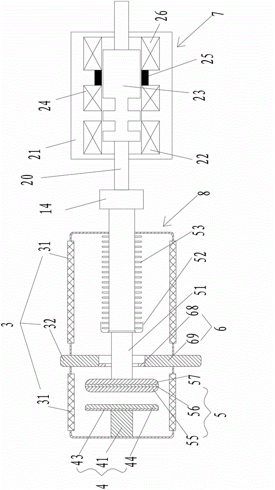
[0039] like figure 1 As shown, the three-position switch according to the embodiment of the present invention includes: a connected vacuum interrupter 8 and a tristable permanent magnet operating mechanism 7 , and the vacuum interrupter 8 includes: a moving end conductive rod 51 . The main difference between the present invention and the three-position switch of the existing bistable permanent magnet operating mechanism is: the permanent magnet operating mechanism 7 adopted by the present invention is a permanent magnet operating mechanism with three stable states, which is more stable than the existing bistable The state permanent magnet operating mechanism has one more stable state, that is, the permanent magnet operating mecha...


PUM


Abstract

The invention discloses a three-position switch. The switch comprises a vacuum extinction chamber and a tristable permanent magnetic operating mechanism, wherein the vacuum extinction chamber and the tristable permanent magnetic operating mechanism are connected, the vacuum extinction chamber comprises a moving end conductive rod, the permanent magnetic operating mechanism (7) comprises a fixing iron core (21), a moving iron core (23), an upper drive coil (22), a middle drive coil (24), a permanent magnet (25), a lower drive coil (26) and a drive rod (20) which is connected to the moving iron core (23), the fixing iron core (21) is provided with an inner cavity, the inner cavity comprises an upper end face, a lower end face and a cylindrical moving iron core moving space arranged between the upper end face and the lower end face, two ends of the drive rod (20) extend out of the fixing iron core, and the moving iron core (23) can be arranged in the moving iron core moving space in a moving mode and is provided with a first working position, a second working position and a third working position.

Description

technical field [0001] The invention relates to the technical field of electric power distribution equipment, in particular to a three-position switch. Background technique [0002] The load switch in the ring network cabinet generally requires three positions, that is, three working positions: 1. The closing position where the main breakout of the isolation switch is connected, 2. The isolation position where the main breakout is separated, and 3. The grounding position on the grounding side. The gas generating type, compressed gas type and SF6 type load switch are easy to realize three positions. For vacuum circuit breakers or vacuum load switches, because the vacuum interrupter can only be disconnected and cannot be isolated, a three-position switch is generally added in front of the circuit breaker or load switch of the vacuum ring network cabinet to form an isolation fracture. Three-position switch, English abbreviation 3PS, that is, 3 position switchgear. The three-p...

Claims


Application Information

Patent Timeline
Patent Type & Authority Applications(China)
IPC IPC(8): H01H3/28
Inventor 闵伟吴健范永强郭彦峰庞腊成王洪浩付永长易平
Owner BEIJING ELECTRIC POWER RES INST HUAYUANELECTRIC POWER TECH
Why Eureka
Try Eureka