
Driving mechanism

A driving mechanism and driving coil technology, applied in the protection switch operation/release mechanism and other directions, can solve the problems of inaccurate control and complex structure, and achieve the effects of good controllability, small size and small action dispersion.

Active Publication Date: 2015-05-13
南瑞智能配电技术有限公司 +1
View PDF3 Cites 3 Cited by
  • Summary
  • Abstract
  • Description
  • Claims
  • Application Information

AI Technical Summary

Problems solved by technology

[0009] The present invention provides a driving mechanism to solve the problems of complex structure and inaccurate control caused by the switching and maintaining of the three working positions in the prior art, which requires the assistance of springs and other components, especially to solve the problem that the working position is in the The middle position in the static iron core needs the assistance of springs and other components to achieve control

Method used


Image

  • Driving mechanism
  • Driving mechanism
  • Driving mechanism

Examples


Embodiment Construction

[0041] In order to have a clearer understanding of the technical features, purposes and effects of the present invention, the specific implementation manners of the present invention will now be described with reference to the accompanying drawings.

[0042] Figure 4 The structure of the first driving mechanism according to the embodiment of the present invention is shown, the driving mechanism includes: a static iron core 1, a moving iron core 2, an upper driving coil 3, a permanent magnet 5 and a lower driving coil 6, the static The iron core 1 has an inner cavity 101, and the inner cavity 101 includes: an upper end surface 1011, a lower end surface 1013, and a cylindrical moving iron core moving space between the upper end surface and the lower end surface, and the moving iron core 2. It is movable and arranged in the moving space of the moving iron core and has at least a first working position. The upper driving coil 3, the permanent magnet 5 and the lower driving coil 6...


PUM


Abstract

The invention provides a driving mechanism, which comprises a static iron core, a movable iron core, an upper drive coil, a permanent magnet and a lower drive coil, wherein the static iron core is provided with an inner cavity, the inner cavity comprises an upper end surface, a lower end surface and a cylindrical movable iron core moving space positioned between the upper end surface and the lower end surface, the movable iron core can be movably arranged in the movable iron core moving space and is at least provided with a first working position, and the upper drive coil, the permanent magnet and the lower drive coil are respectively sleeved on the outer part of the movable iron core moving space. In the first working position, a first annular boss and a fourth annular boss are mutually matched to form a magnetic circuit in the radial direction, the upper end surface of the movable iron core is far away from the upper end surface of the inner cavity, and the lower end surface of the movable iron core is far away from the lower end surface of the inner cavity.

Description

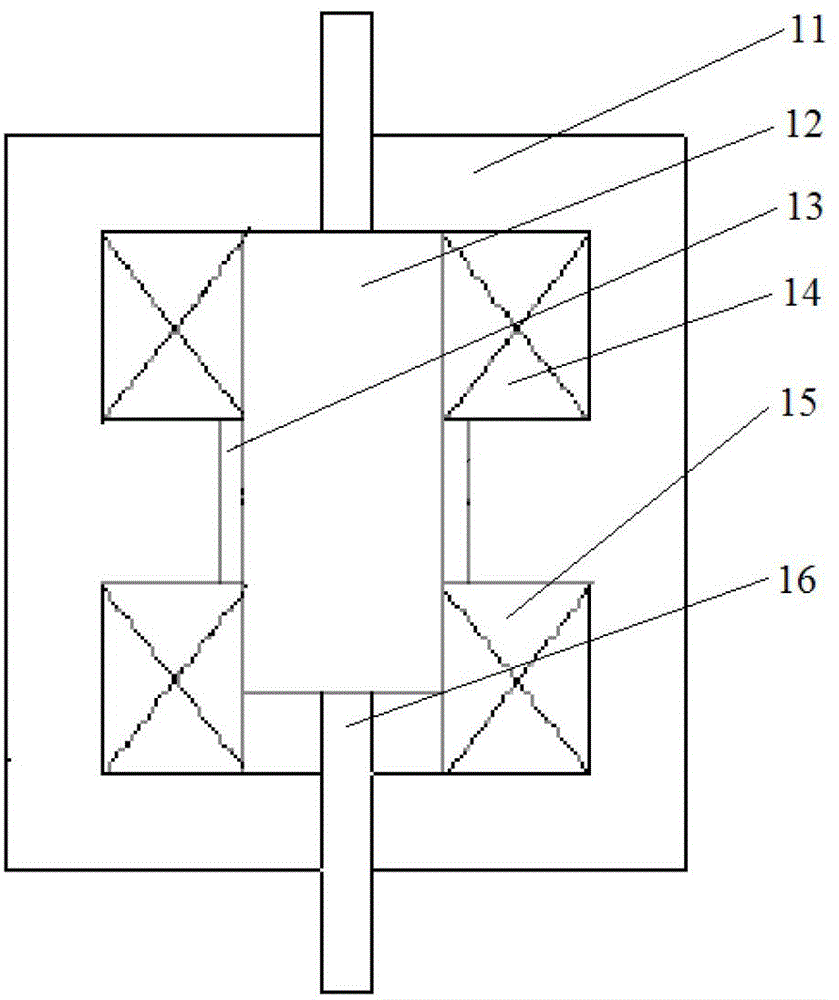
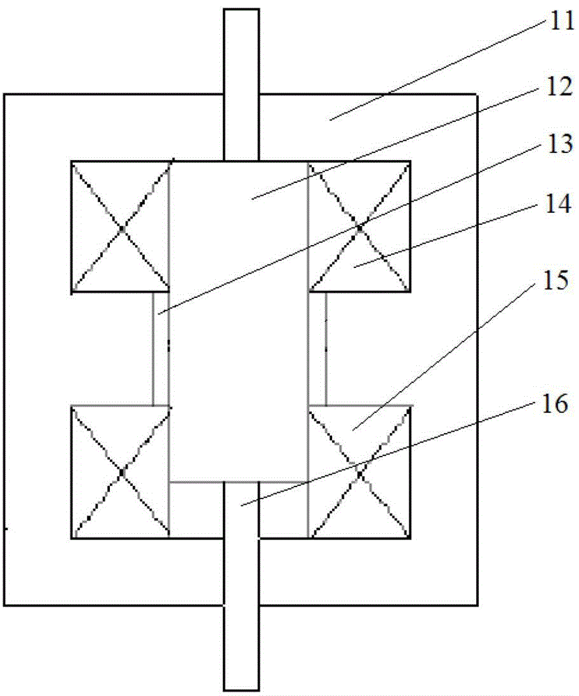
technical field [0001] The invention relates to the field of drive equipment technology or electrical control, in particular to a drive mechanism, especially a tristable permanent magnet operating mechanism. Background technique [0002] Existing permanent magnet operating mechanisms are mainly divided into bistable permanent magnet mechanisms and monostable permanent magnet mechanisms in principle, the principles of which are briefly introduced below. [0003] Firstly, the principle of the bistable permanent magnet operating mechanism is introduced. The so-called bistable state refers to the two positions of the moving iron core at the end of the stroke, which can be maintained without mechanical locks. figure 1 It is a schematic diagram of the structure and principle of an existing bistable permanent magnet operating mechanism, such as figure 1 As shown, the bistable permanent magnet operating mechanism has seven main parts: 11 is the static iron core, which provides the...

Claims


Application Information

Patent Timeline
Patent Type & Authority Patents(China)
IPC IPC(8): H01H71/10
Inventor 闵伟张力庞腊成张重乐付永长易平黄志军陈立民张峰涛周云祥
Owner 南瑞智能配电技术有限公司
Learn More