AI technical title is built by Patsnap AI team. It summarizes the technical point description of the patent document.
A nozzle and rotary chamber technology, applied in the direction of injection device, injection device, liquid injection device, etc., can solve the problems of turbulent flow, large resistance, reduced flow rate of content, etc., to achieve less spray volume, increased rotation speed, and small nozzle diameter. Effect
Active Publication Date: 2015-12-16
DAIZO
View PDF8 Cites 0 Cited by
Summary
Abstract
Description
Claims
Application Information
AI Technical Summary
This helps you quickly interpret patents by identifying the three key elements:
Problems solved by technology
Method used
Benefits of technology
Problems solved by technology
However, since the spout is small, the resistance applied to the contents in the vicinity of the spout is large, the flow velocity of the contents near the spout is reduced, the flow is greatly disturbed, and it is directly discharged in a rod shape.
Method used
Image
Click on the blue label to locate the original text in one second.
Reading with bidirectional positioning of images and text.
Examples
Embodiment 1
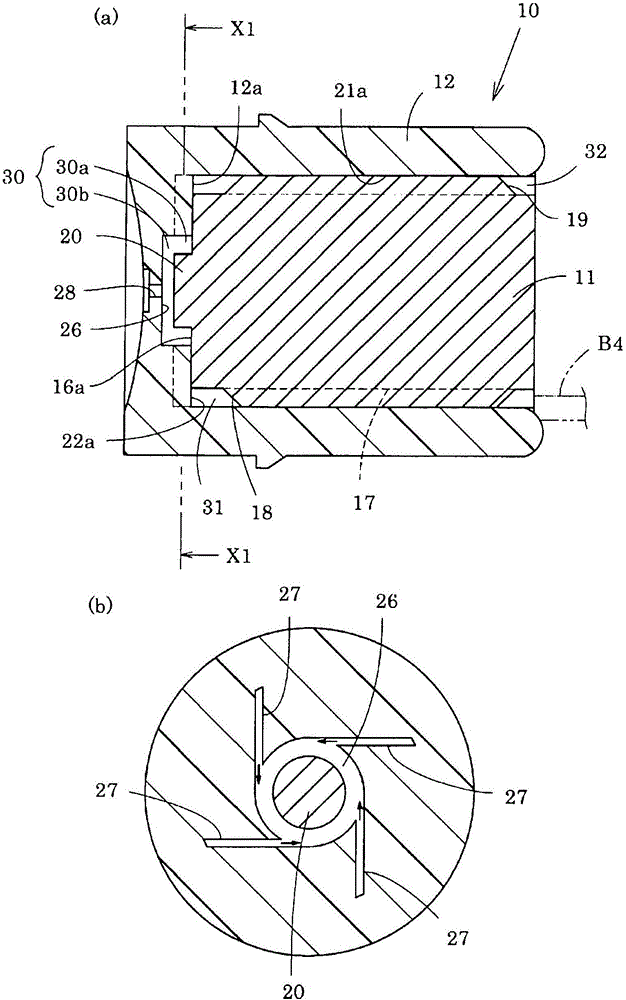
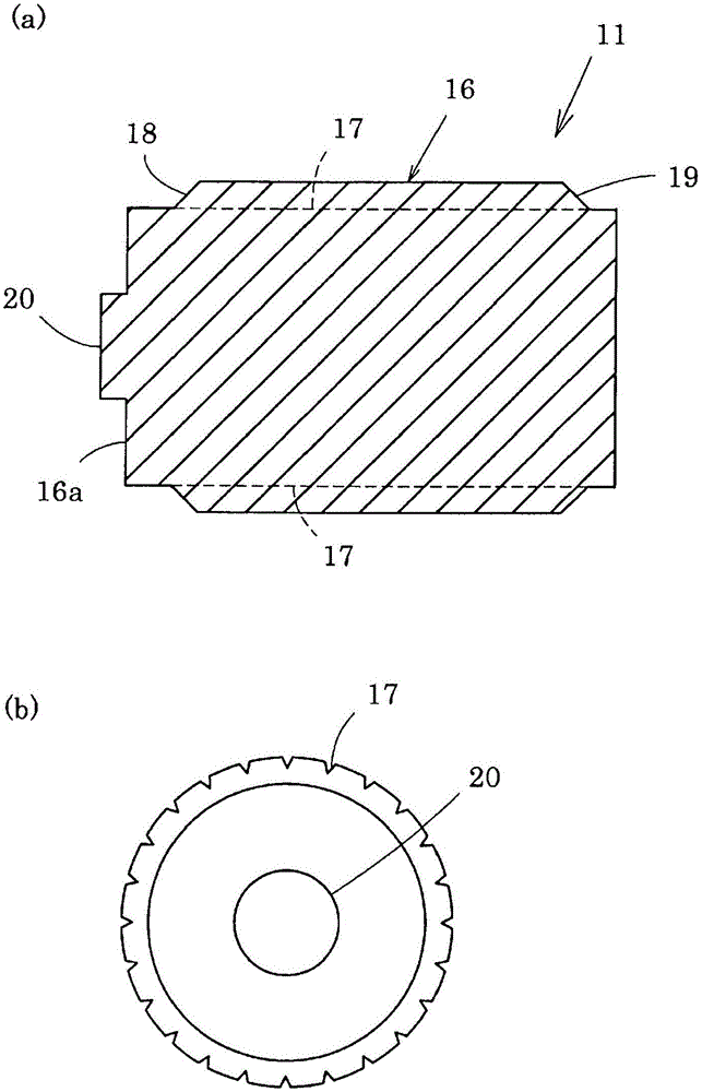
[0068] Protruding portion 20 of core 11: outer diameter 1.5 mm, height 0.2 mm
[0069] Recess 26 of nozzle member 12: inner diameter 2.0 mm, height 0.4 mm, nozzle diameter 0.15 mm
[0071] In this spout mechanism 10, the outer diameter of the protruding portion 20 is 75% of the inner diameter of the recessed portion 26, the height of the protruding portion 20 is 50% of the height of the recessed portion 26, and the area ratio of the passage to the spout is 6.8.
Embodiment 2
[0073] Protruding portion 20 of core 11: outer diameter 1.5 mm, height 0.05 mm
[0074] Recess 26 of nozzle member 12: inner diameter 2.0 mm, height 0.4 mm, nozzle diameter 0.15 mm
[0076] In this spout mechanism 10, the outer diameter of the protruding portion 20 is 75% of the inner diameter of the recessed portion 26, the height of the protruding portion 20 is 15% of the height of the recessed portion 26, and the area ratio of the passage to the spout is 6.8.
[0081] In this spout mechanism 10, the outer diameter of the protruding portion 20 is 37.5% of the inner diameter of the recessed portion 26, the height of the protruding portion 20 is 50% of the height of the recessed portion 26, and the area ratio of the passage to the spout is 6.8.
PUM
Abstract
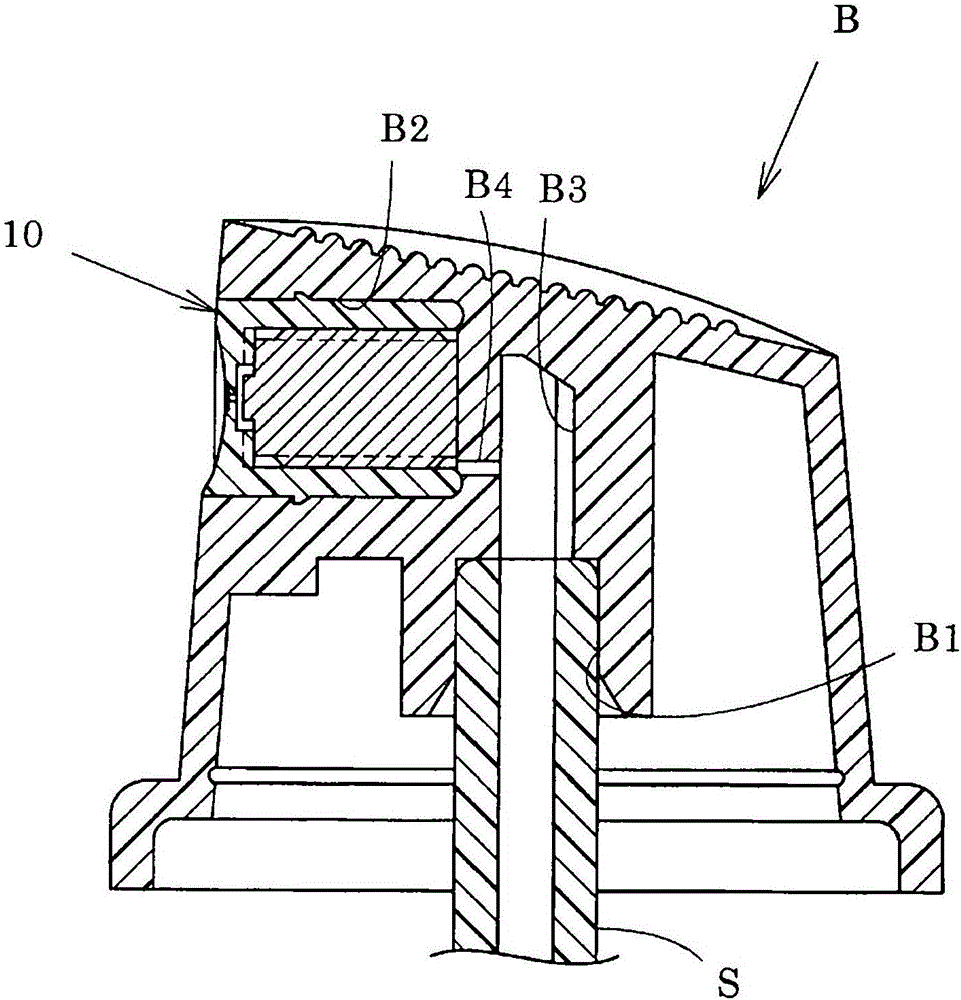
A nozzle hole mechanism (10) is provided with a nozzle hole (28) which ejects a concentrate into the atmosphere, a swirl chamber (30) which supplies the concentrate to the nozzle hole (28), and a path (27) which supplies the concentrate to the swirl chamber (30). The diameter of the nozzle hole (28) is 0.2 mm or less, the length of the nozzle hole (28) is in the range of 0.05-0.3mm, and the swirl chamber (30) and the nozzle hole (28) are located on the same axis. The swirl chamber (3) is equipped with a front section having a solid cylindrical shape, which communicates with the nozzle hole, and a rear section having an ring shape. The nozzle hole mechanism is configured in such a manner that the concentrate is supplied to the rear section (30a) and discharged from the nozzle hole (28) via the front section (30b). The configuration enables the nozzle mechanism to spray fine particles over a wide area using small spray amount.
Description
technical field [0001] The present invention relates to spout mechanisms. Specifically, it relates to a nozzle mechanism attached to an injection member of spray products such as atomization products and pump products. Background technique [0002] For products that pressurize and discharge the content (stock solution) in a container, such as atomization products and pump products, there is known a nozzle mechanism that discharges (sprays) the discharged content in the form of a fine mist. [0003] Patent Document 1 discloses a nozzle mechanism for atomized products including a mechanical break mechanism in which a conical swirling chamber is provided inside the nozzle. The spout mechanism has a spray groove formed in contact with the outer peripheral edge of the swirl chamber, and the content is introduced into the swivel chamber through the spray groove. Therefore, the contents are sprayed out from the nozzle port in a state of swirling in the swirling chamber. Thereby,...
Claims
Application Information
Patent Timeline
Application Date:The date an application was filed.
Publication Date:The date a patent or application was officially published.
First Publication Date:The earliest publication date of a patent with the same application number.
Issue Date:Publication date of the patent grant document.
PCT Entry Date:The Entry date of PCT National Phase.
Estimated Expiry Date:The statutory expiry date of a patent right according to the Patent Law, and it is the longest term of protection that the patent right can achieve without the termination of the patent right due to other reasons(Term extension factor has been taken into account ).
Invalid Date:Actual expiry date is based on effective date or publication date of legal transaction data of invalid patent.

