Power generation element and power generation apparatus provided with power

A technology of power generation components and magnetostrictive rods, applied in the direction of electrical components, generators/motors, piezoelectric effect/electrostrictive or magnetostrictive motors, etc., can solve the problems of low power generation efficiency and achieve power generation Multiple and durable effects

Active Publication Date: 2013-03-20
KANAZAWA UNIV
View PDF4 Cites 5 Cited by
  • Summary
  • Abstract
  • Description
  • Claims
  • Application Information

AI Technical Summary

Problems solved by technology

In addition, since the compressive force is unevenly applied to the magnetostrictive material, there is a disadvantage that the power generation efficiency becomes low

Method used


Image

  • Power generation element and power generation apparatus provided with power
  • Power generation element and power generation apparatus provided with power
  • Power generation element and power generation apparatus provided with power

Examples


Embodiment approach 1

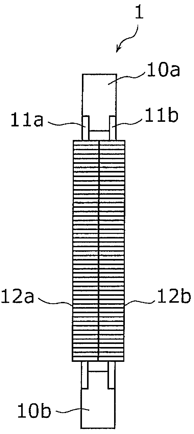
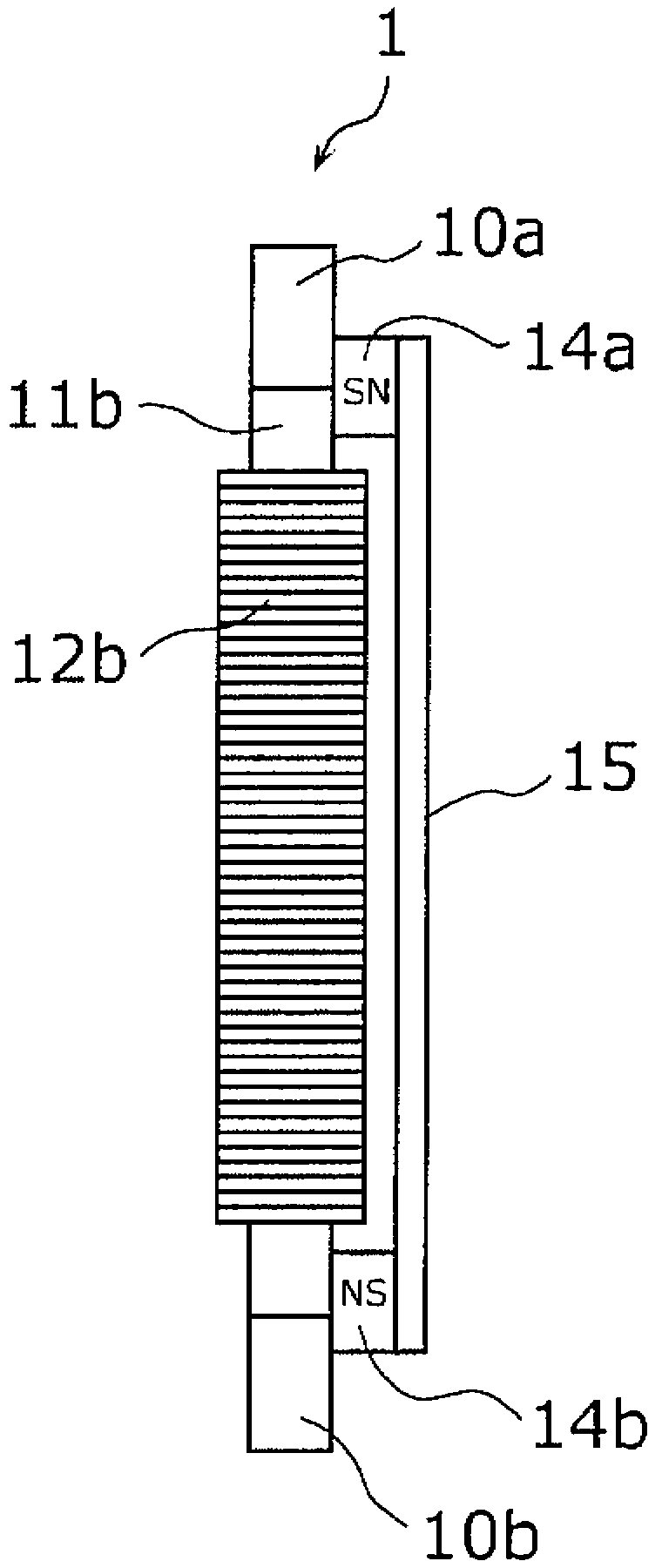
[0109] Figure 1A is a plan view of a power generating element according to an embodiment of the present invention, Figure 1B It is a side view of the power generating element according to one embodiment of the present invention. Such as Figure 1A and Figure 1BAs shown, the power generating element 1 includes connection yokes 10 a and 10 b , magnetostrictive rods 11 a and 11 b , coils 12 a and 12 b , permanent magnets 14 a and 14 b , and a back yoke 15 .

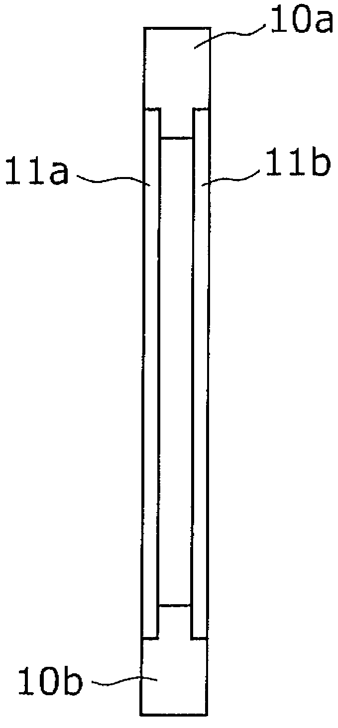
[0110] Figure 2A and Figure 2B yes means Figure 1A and Figure 1B A schematic diagram of the arrangement positions of the magnetostrictive rods 11a and 11b and the connecting yokes 10a and 10b of the power generating element 1 shown, Figure 2A and Figure 2B corresponding to Figure 1A and Figure 1B .

[0111] The magnetostrictive rods 11 a and 11 b are made of, for example, Galfenol which is an iron-gallium alloy, have ductility, and each have a rectangular parallelepiped rod shape of 1 mm×0.5 mm×10 mm.

[0...

Embodiment approach 2

[0186] Next, Embodiment 2 which is one embodiment of the present invention will be described. In Embodiment 1 described above, the power generating element is constituted by two magnetostrictive rods, but this embodiment is different from Embodiment 1 in that the power generating element is constituted by one magnetostrictive rod and a connecting yoke.

[0187] Figure 11A is a side view of the power generating element of this embodiment, Figure 11B yes means Figure 11A A side view of the arrangement position of the magnetostrictive rod and the connecting yoke of the power generating element shown.

[0188] Such as Figure 11A As shown, the power generating element of this embodiment includes a magnetostrictive rod 11c, a connecting yoke 10c, and a coil 12c. In addition, the magnetostrictive rod 11c and the coil 12c correspond to the 1st magnetostrictive rod and the 1st coil of this invention, respectively.

[0189] The magnetostrictive rod 11c is the same as the magnet...

Embodiment approach 3

[0194] Next, Embodiment 3 which is one embodiment of the present invention will be described. In this embodiment, a power generating element in which a plurality of coils are wound in parallel around each magnetostrictive rod will be described. Figure 12A ~ Figure 12D is a plan view of the power generating element of this embodiment, Figures 13A-13G yes Figure 12A ~ Figure 12D Equivalent circuit diagram of the power generating element shown. In addition, in Figure 12A ~ Figure 12D In , the coils 12a and 12b are shown as cross-sectional views.

[0195] Figure 12A The power generating element 1 shown is with Figure 1A The power generating element 1 shown has the same structure, and the basic structure of the power generating element 1 is shown. In this power generating element 1, one coil 12a and 12b are respectively wound around the magnetostrictive rods 11a and 11b. According to this configuration, by dividing the coils and connecting them in parallel, it is possib...


PUM


Abstract

Disclosed are: a power generation element that has a strong resistance against bending and impact, and that generates a large amount of power; and a power generation apparatus provided with the power generation element. The power generation element (1) is provided with a first magnetostriction rod (11a) comprised of a magnetostrictive material; a rigid rod (11b) that is comprised of a magnetic material having rigidity and shape necessary for applying a uniform compressive / tensile force to the first magnetostriction rod (11a), and that is arranged to be parallel with the first magnetostriction rod (11a); a first coil (12c) wound around the first magnetostriction rod (11a); and two interconnecting yokes (10a, 10b) arranged at both ends of the first magnetostriction rod (11a) and the rigid rod (11b) such that the two rods are interconnected. Power is generated, by having the first magnetostriction rod (11a) expanded or contracted with the vibration thereof in a direction perpendicular to the axis direction thereof.

Description

technical field [0001] The present invention relates to a power generating element utilizing vibration, and more particularly to a power generating element using a magnetostrictive material. Background technique [0002] Conventionally, the development of a technology for generating power from vibrations around the body has been actively promoted. As one of such technologies, a power generation method using a piezoelectric element and a power generation method using a change in magnetic flux density of a permanent magnet are known. [0003] In many methods of generating electricity using a piezoelectric element, power is generated by applying force to the piezoelectric element from the outside by a certain method to deform the piezoelectric element. In order to deform a piezoelectric element, there are, for example, a method of applying vibration to a piezoelectric element to deform it, a method of indirectly applying pressure such as wind pressure or sound pressure, a metho...

Claims


Application Information

Patent Timeline
Patent Type & Authority Applications(China)
IPC IPC(8): H02N2/00
CPCH02N2/188H02N2/185H01L41/125H10N35/101H02N2/00H10N35/80
Inventor 上野敏幸池畑芳雄山田外史
Owner KANAZAWA UNIV
Why Eureka
Try Eureka