Filtering sieve shaft of sieving machine

A sieving machine and sieve shaft technology, which is applied in the direction of filter screen, solid separation, grille, etc., can solve the problem of material blocking prevention

Active Publication Date: 2013-03-27
SICHUAN ZHONGMENG ELECTRIC POWER EQUIP MFG CO LTD
View PDF7 Cites 7 Cited by
  • Summary
  • Abstract
  • Description
  • Claims
  • Application Information

AI Technical Summary

Problems solved by technology

[0009] The purpose of the present invention is to solve the deficiencies in the technology of the existing invention of the cloth screening machine ZL: 2111 1 01

Method used


Image

  • Filtering sieve shaft of sieving machine
  • Filtering sieve shaft of sieving machine
  • Filtering sieve shaft of sieving machine

Examples


Embodiment 1

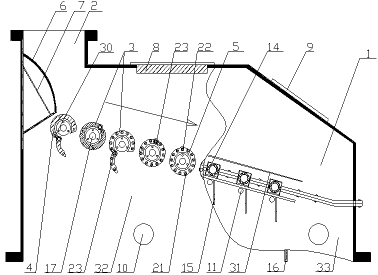
[0067] Embodiment 1: as figure 1 , figure 2As shown, the screening machine includes feed inlet 2, sieve shaft 3, flange-type sieve shaft 4, bar-type sieve shaft 5, arc distribution plate 6, distribution plate support 7, iron remover 8, inspection cover 9 , Particle size observation hole 10, sieve bar replacement hole 11, gear motor 12, gear 13, sealed bearing 14, support frame 15, particle size guide plate 16, transmission shaft 17, flange piece 18, reinforcement ring 19, clip bar 20. Sieve bar 21, sieve slit enlarged hole 22, filter sieve shaft bearing 23, sieve slit 25, bearing cover plate 29, qualified particle size discharge port 30, coarse particle size discharge port 31. The material is in the shape of a water column and falls from a high place onto the arc-shaped distribution plate 6 on the inner wall of the feed inlet 2, breaking the water column to complete the first distribution, and then the material falls on the flange plate sieve shaft 4, breaking the oval shape...

Embodiment 2

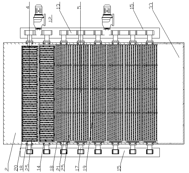
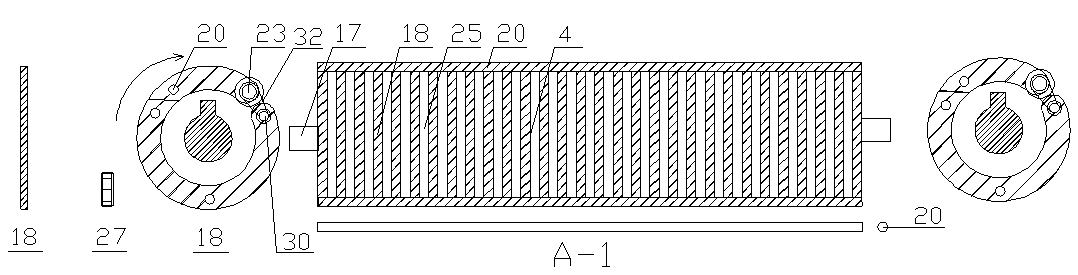
[0068] Embodiment 2: as image 3 As shown, the flange plate type screen shaft 4 includes flange plate 18, screen slot gap nut 27, filter screen shaft bearing 23, clip bar 20, transmission shaft 17, and is combined into a flange type screen shaft with screen slot 25 Screen shaft 4. The main functions of the flange plate screen shaft are impact resistance, conveying, material distribution, and screening; image 3 Obviously, the flange plate type screen shaft 4 is cut into several pieces of two groups of flange plate type screen shafts by several circular flange plates 18. One set of flanged screen shafts is fixed, while the other set of flanged screen shafts is movable. There are clips in the movable holes of the flanges 18 on the movable screen shafts. The clips 20 are String all the movable flanges on the top to form a movable half screen shaft. There are two kinds of activities on the movable half screen shaft. One uses the rotating screen shaft bearing 23, and the other us...

Embodiment 3

[0069] Embodiment 3: as Figure 4 , Figure 5 , Figure 6 , Figure 7 As shown, the sieve type sieve shaft includes a flange 18, a reinforcing ring 19, a sieve bar 21, a drive shaft 17, a filter sieve shaft bearing 23, a sieve slit enlargement hole 22, and a chain 28 to form a belt sieve 25 and a belt sieve hole. The sieve type sieve shaft 5. From Figure 4 , Figure 5 , Figure 6 , Figure 7 It is obvious that the sieve-type sieve shaft 5 is composed of flanges 18 and sieve bars 21, and the sieve-type sieve shaft 5 is also composed of two flanges with sieve bars 21 to form a circular sieve-type sieve shaft 5. One of the flanges with sieve bars is fixed, while the other flange with sieve bars is active. In the sieve type sieve shaft 5, a sieve shaft reinforcement ring 19 consistent with the flange sheet parameters is also provided, and the number of the reinforcement ring in each sieve type sieve shaft is 2-10; each sieve bar material, The diameter and length are not ...


PUM


Abstract

The invention discloses a filtering sieve shaft of a sieving machine. The filtering sieve shaft comprises a sieving face composed of a movable flange plate type sieve shaft (4), a movable sieving strip type sieve shaft (5) and a spring type sieve shaft (24). The filtering sieve shaft has the advantages of guaranteeing sieving granular size and solving the problem that materials are not blocked in the hollow filtering sieve shaft. The filtering sieve shaft has the advantages of being good in anti-impact capacity, efficient in sieving, capable of guaranteeing granular size, free of material blocking, capable of removing iron, even in material distribution, capable of meeting requirements of more than two discharging granular sizes, convenient to overhaul, favorable for replacing parts and the like and is major breakthrough in the field of the sieving machine.

Description

technical field [0001] The invention relates to a coarse and fine separation device, in particular to a filter shaft in a screening machine. Background technique [0002] It is well known that the coarse and fine separation equipment screening machine is used in coal, chemical industry, metallurgy, mining, coking, building materials, raw materials, grain and other industries. The filter shaft of the sieving machine is especially suitable for coarse and fine separation in the fuel system of circulating fluidized bed boilers in thermal power plants. The combustion of circulating fluidized bed boilers is coal gangue with a certain particle size, and the particle size of coal from coal mines is uneven, but most of the materials do not need repeated crushing, and this part of the materials generally accounts for about 35-75% %. If this part of the qualified particle size material is screened out, it will bring many benefits to the subsequent working conditions. [0003] At pre...

Claims


Application Information

Patent Timeline
IPC IPC(8): B07B1/14B07B1/42B07B1/46
Inventor 马琳
Owner SICHUAN ZHONGMENG ELECTRIC POWER EQUIP MFG CO LTD
Why Eureka
Try Eureka