
Die elevating device applied to tube bending machine

The technology of a lifting device and a pipe bender is applied in the field of mold lifting devices, which can solve the problems of easy damage of the lead screw, inability to run, insufficient power and so on.

Inactive Publication Date: 2013-03-27
张家港和升数控机床制造有限公司
View PDF4 Cites 3 Cited by
  • Summary
  • Abstract
  • Description
  • Claims
  • Application Information

AI Technical Summary

Problems solved by technology

However, in this form of using the lead screw for lifting, on the one hand, the lead screw is easy to be damaged after long-term use; To the vertical force, the servo motor connected to the lead screw will be subjected to a force exceeding its rated load, causing the servo motor to alarm
The servo motor stops, resulting in the failure of the subsequent processes of pipe bending
And the bent pipe fittings are stuck in the pipe bending mold, resulting in the scrapping of the pipe fittings
In addition, if the servo motor works for a long time, its power will be insufficient, resulting in insufficient movement accuracy of the lead screw

Method used


Image

  • Die elevating device applied to tube bending machine
  • Die elevating device applied to tube bending machine
  • Die elevating device applied to tube bending machine

Examples


Embodiment Construction

[0016] Specific embodiments of the present invention will be described in detail below in conjunction with the accompanying drawings.

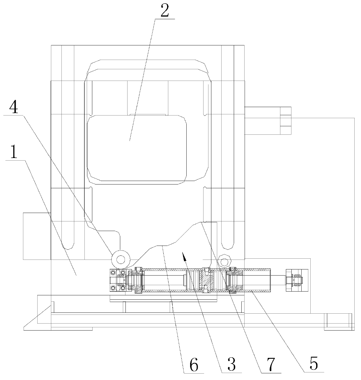
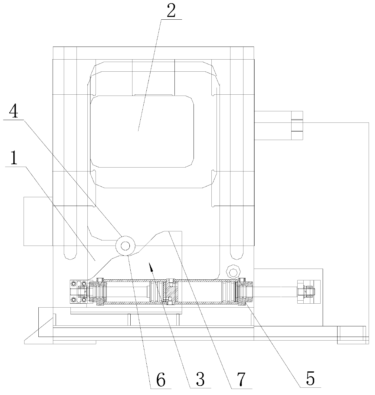
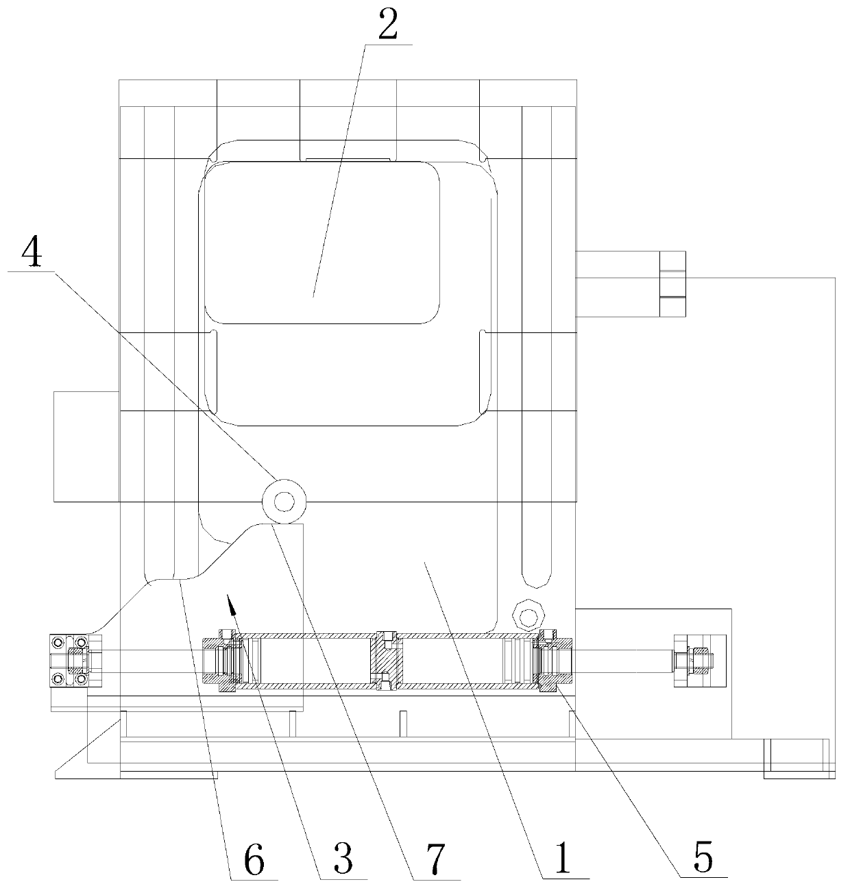
[0017] Such as figure 1 figure 2 image 3 As shown, a mold lifting device for a pipe bending machine includes a body 1, a mold seat 2 that can slide up and down is installed on the body 1, and a wedge 3 that can slide horizontally is installed on the bottom of the body 1. The upper surface of the wedge 3 is provided with at least one layer of steps with a slope on one side. The specific number of steps depends on actual needs. In this embodiment, two steps are used, that is, the wedge 3 has 3 layers for the roller 3 to roll. platform. The lower end of the mold base 2 is provided with a roller 4, which is in contact with the upper surface of the wedge 3 and can roll from the upper surface of the wedge 3 to the step. The mold base 2 is installed on the fuselage 1 through slide rails on both sides. In order to minimize the resistance of the...


PUM


Abstract

The invention discloses a die elevating device applied to a tube bending machine. The die elevating device comprises a machine body, wherein a die base which can slide up and down is installed on the machine body; a wedge block which can slide horizontally is installed at the bottom part of the machine body; stairs are arranged on the surface of the wedge block; the die base is provided with a roller; and the roller is arranged on the stairs of the wedge block. The wedge block horizontally slides so as to push the roller to be positioned in stairs of different layers. The wedge block adopts a fixing mode that two oil cylinders are connected tail to tail. The die base is pushed to move up and down by using the horizontal movement of the wedge block, such mode of push is more stable and unlikely to damage compared with a screw rod mode; and the fixation mode that two oil cylinders are connected tail to tail ensures that the wedge block is stable and positioned in place.

Description

technical field [0001] The invention relates to a mold lifting device for a pipe bending machine. Background technique [0002] In the existing mold lifting device for pipe bending machines, the mold base mainly depends on the action of the motor and the lead screw to lift up and down along the fuselage. However, in this form of using the lead screw for lifting, on the one hand, the lead screw is easily damaged after long-term use; To the force in the vertical direction, the servo motor connected to the lead screw will be subjected to a force exceeding its rated load at this time, causing the servo motor to alarm. The servo motor stopped, resulting in the inoperability of several subsequent processes of pipe bending. And the bent pipe fittings are stuck in the pipe bending mold, thus causing the pipe fittings to be scrapped. In addition, if the servo motor works for a long time, its power will be insufficient, resulting in insufficient movement accuracy of the lead screw....

Claims


Application Information

Patent Timeline
Patent Type & Authority Applications(China)
IPC IPC(8): B21D9/16
Inventor 袁林飞
Owner 张家港和升数控机床制造有限公司
Learn More