Cylindrical member enclosure riveting mold

A riveting mold and cylinder technology, applied in the field of riveting molds, can solve the problems of inconvenient riveting of cylindrical parts, and achieve the effect of improving the qualified rate of riveting, convenient pick and place, and simple structure

Inactive Publication Date: 2013-03-27
昌辉汽车电器(黄山)股份公司
View PDF7 Cites 3 Cited by
  • Summary
  • Abstract
  • Description
  • Claims
  • Application Information

AI Technical Summary

Problems solved by technology

[0003] The purpose of the present invention is to provide a riveting die for cylindrical parts, which solves the problem that the existing riveting die moves from top to bottom and is inconvenient for riveting cylindrical parts with complex structures

Method used


Image

  • Cylindrical member enclosure riveting mold
  • Cylindrical member enclosure riveting mold
  • Cylindrical member enclosure riveting mold

Examples


Embodiment Construction

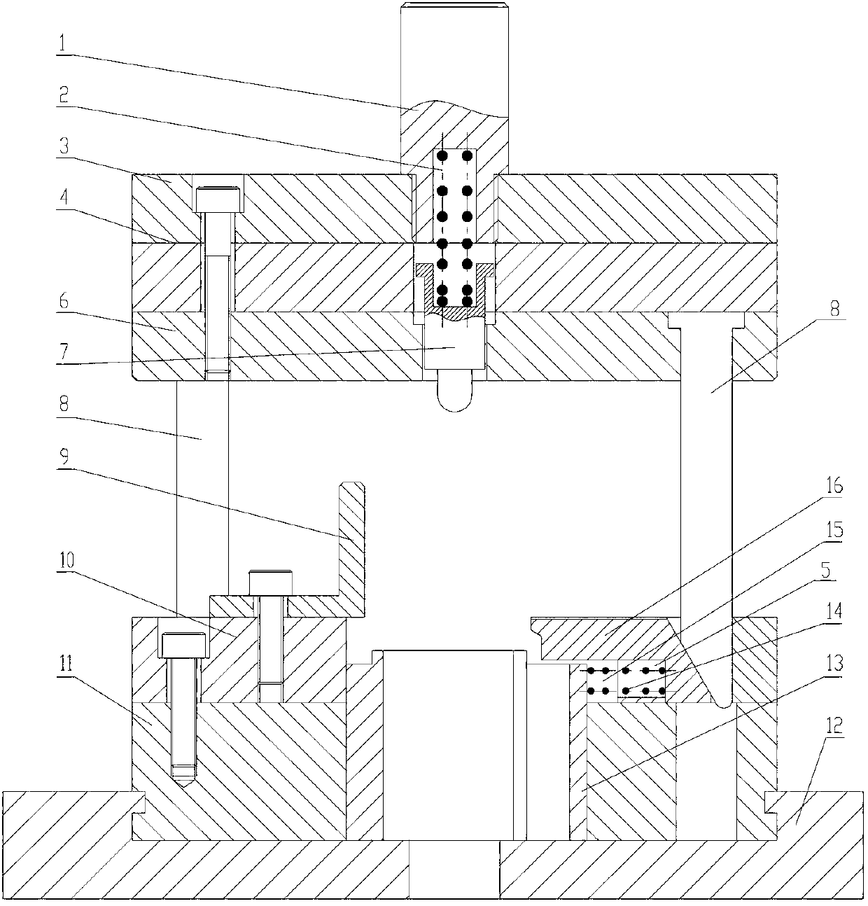
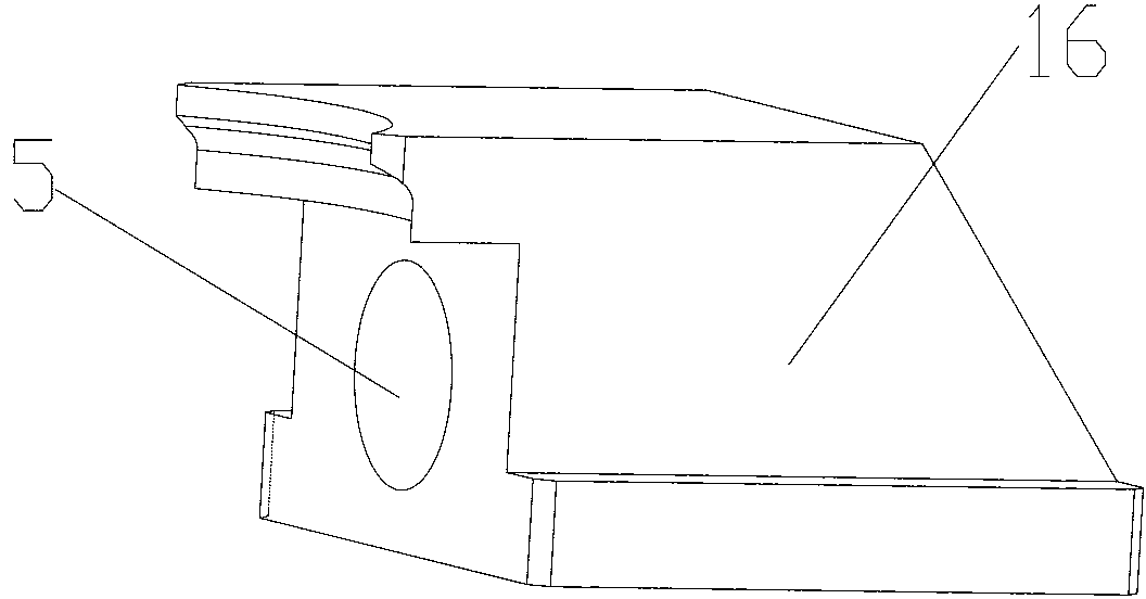
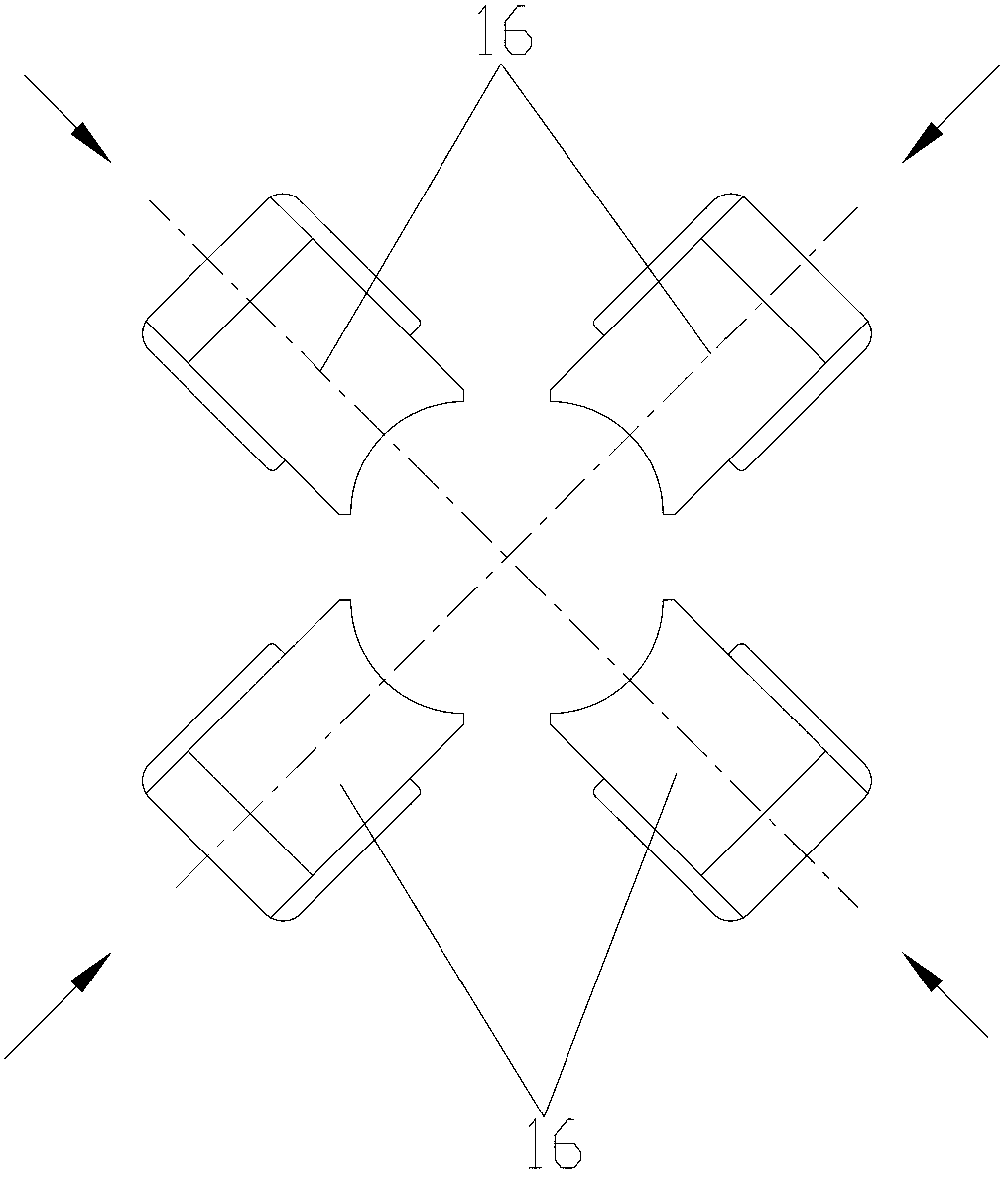
[0016] Examples such as Figures 1 to 4 As shown, a cylindrical part riveting mold includes an upper mold and a lower mold. The lower mold is provided with a bracket cover 13, and a group of riveting heads 16 of the riveting workpiece are arranged on the lower mold. The riveting head 16 is riveted The ends are closed to form a circle; the other end of the riveting head 16 is a slope structure, and the upper mold is provided with a group of slanting wedges 8 matched with the rivet 16, and the vertical movement of the slanting wedge 8 squeezes the rivet 16 to realize The lateral movement of the riveting head 16 causes the riveting head 16 to encircle the riveted workpiece in the middle. More specifically, there are four riveting heads 16 evenly arranged, and there are also four matching oblique wedges 8; the riveting head 16 A return stage clip 14 is also provided with the lower die. Described lower die comprises bottom plate 12, the supporting plate 11 that is fixed on the bot...


PUM


Abstract

The invention discloses a cylindrical member enclosure riveting mold, which comprises an upper die and a lower die, wherein the lower die is provided with a tray sleeve on the lower die; a group of riveting heads for realizing riveting press of a workpiece are arranged on the lower die; riveting ends of the riveting heads are enclosed to be circular; the other ends of the riveting heads are of inclined plane structures; the upper die is provided with a group of oblique wedges which are matched with the riveting heads; the riveting heads are squeezed by vertical motion of the oblique wedges to realize transverse movement of the riveting heads, so that the riveting heads enclose to the middle to rivet the workpiece; and a return compression spring is also arranged between the riveting heads and the lower die. According to the cylindrical member enclosure riveting mold, the problem of difficulty in riveting of a large-sized workpiece of a complex structure is solved, particularly, the riveting of the middle part of the workpiece with two large ends and small middle part cannot be realized through the conventional vertical movement riveting; vertical movement of the upper die is converted into horizontal movement of the riveting heads, so that riveting of the middle part is realized; and thus, the cylindrical member enclosure riveting mold is safe and reliable and can be widely applied to the field of the riveting mold.

Description

technical field [0001] The invention relates to a riveting die, in particular to a cylindrical part riveting die. Background technique [0002] Usually, in the circular riveting process, the riveting head is made into a 360° ring, which is set on the workpiece, and under the vertical pressure of the press, it moves back and forth in one direction to rivet. If some workpieces with complex structures such as: two large ends, small middle, and the riveting position is in the middle workpiece, when riveting, the riveting difficulty will be greatly improved. Especially for the riveting of cylinders, it is more difficult to move riveting in the vertical direction. Contents of the invention [0003] The purpose of the present invention is to provide a riveting die for cylindrical parts, which solves the problem that the existing riveting die moves riveting from top to bottom and is inconvenient for riveting cylindrical parts with complex structures. [0004] The technical solut...

Claims


Application Information

Patent Timeline
Patent Type & Authority Applications(China)
IPC IPC(8): B21D37/10B21D39/00
Inventor 王进丁王正成朱排进李宏志
Owner 昌辉汽车电器(黄山)股份公司
Why Eureka
Try Eureka