Pneumatic cutting nipper using single dynamic elastomer

A technology of pneumatic cutting pliers and power bombs, which is applied in the field of pneumatic cutting pliers to achieve the effects of easy manufacture, reduced speed and simple structure

Inactive Publication Date: 2014-12-03
710TH RES INST OF CHINA SHIPBUILDING IND CORP
View PDF7 Cites 0 Cited by
  • Summary
  • Abstract
  • Description
  • Claims
  • Application Information

AI Technical Summary

Problems solved by technology

This kind of pneumatic cutter does not use a compression spring, and the moving knife and the fixed knife are not in close contact with the object to be cut.

Method used


Image

  • Pneumatic cutting nipper using single dynamic elastomer

Examples


Embodiment Construction

[0014] The specific implementation of the present invention will be further described below in conjunction with the accompanying drawings and examples. The following examples are only used to illustrate the technical solutions of the present invention more clearly, but not to limit the protection scope of the present invention.

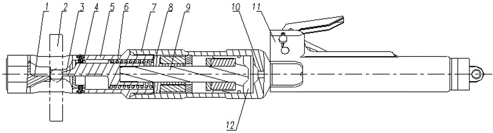
[0015] Such as figure 1 As shown, the technical solution of the present invention is: a pneumatic cutter using a single power spring, including a fixed knife 1, a moving knife 3, a tool holder 5, a compression spring 6, a cylinder block 7, a guide sleeve 8, a piston 9. Power bomb 10 and firing device 11;

[0016] Wherein, the cutout portion of the movable knife 3 is a semicircular structure;

[0017] A guide hole is formed on the right part of the knife rest 5;

[0018] A chamber is provided at the rear end of the cylinder block 7;

[0019] The connection relationship is: the fixed knife 1 is installed on the left side of the knife holder 5, the pi...


PUM


Abstract

The invention belongs to the technical field of pneumatic tools, and specifically relates to a pneumatic cutting nipper which is used for cutting objects such as reinforcing bars and steel cables and the like with different diameters by using a thrust generated after high-pressure gas produced directly by using a dynamic elastomer passes through a piston cylinder. The pneumatic cutting nipper comprises a stationary knife, a moving knife, a knife rest, a tight pressing spring, a dynamic elastomer and a triggering device. The pneumatic cutting nipper disclosed by the invention has the advantages that the cutting nipper makes an operation of cutting objects with different diameters by using a dynamic elastomer possible; and the pneumatic cutting nipper is simple in structure, easy to manufacture, and reliable in operation. Due to a larger gas chamber, the speeds of the piston and the moving knife are reduced, the impact is reduced, and the service life is prolonged.

Description

technical field [0001] The invention belongs to the technical field of pneumatic tools, and specifically relates to a pneumatic cutter which directly uses a power bomb to generate high-pressure gas, which generates thrust after passing through a piston cylinder, and is used for cutting objects such as steel bars and cables with different calibers. Background technique [0002] Existing pneumatic scissors are mainly made up of moving knife, fixed knife, knife rest, piston, cylinder, percussion device. Pneumatic cutters sold on the market are in this form. When the object to be cut is placed between the moving knife and the fixed knife, the firing device is pulled to fire the power bomb, and the high-pressure gas pushes the piston and the moving knife to move, and cuts the object to be cut together with the fixed knife. This kind of pneumatic cutter requires the use of different power bullets for objects of different calibers, otherwise it will reduce the life of the pneumati...

Claims


Application Information

Patent Timeline
Patent Type & Authority Patents(China)
IPC IPC(8): B21F11/00
Inventor 祝君旗曹帅辉李智慧寿卫良
Owner 710TH RES INST OF CHINA SHIPBUILDING IND CORP
Why Eureka
Try Eureka