Gear shaft machining method and gear shaft clamping tool used in method

A processing method and technology for gear shafts, which are applied in gear tooth manufacturing devices, components with teeth, metal processing equipment, etc., can solve the problem that the processing accuracy of gear shafts is difficult to meet the design requirements, it is difficult to eliminate processing accuracy errors, and the impact on gear shafts is difficult. Processing quality and other issues, to achieve the effect of not easy radial runout, convenient transportation, and stable loading

Active Publication Date: 2013-03-27
河南蒲瑞精密机械有限公司
View PDF8 Cites 9 Cited by
  • Summary
  • Abstract
  • Description
  • Claims
  • Application Information

AI Technical Summary

Problems solved by technology

Although the existing gear shaft processing jig can clamp the longer gear shaft through the heightened table, and then carry out gear hobbing, but for single-piece, small-batch production of non-standard length gear shafts, manufacturing is difficult. It is very difficult, because the tip is not fixed firmly to the gear shaft, it is difficult to eliminate the machining accuracy error caused by the unstable tip fixation during gear hobbing, so that the machining accuracy of the gear shaft is difficult to meet the design requirements; at the same time, due to The axial span between the upper and lower clamping positions of the gear shaft is relatively large. On the one hand, it is difficult to clamp the upper and lower ends of the gear shaft. The card position is far away, and the gear shaft is also prone to radial runout. The radial runout will affect the processing quality of the gear shaft, and may cause the processing of the gear shaft to be scrapped; and because the length of the gear shaft is long, the gear shaft The height of the processing section from the rotary table is high, which requires that the hobbing head of the vertical gear hobbing machine should have a large up and down movement stroke. Correspondingly, in order to ensure the stability of the hobbing head, it is necessary to increase the height and strength of the column , the strength of the bed needs to be increased accordingly, which makes the entire vertical hobbing machine more bulky and more expensive to manufacture

Method used


Image

  • Gear shaft machining method and gear shaft clamping tool used in method
  • Gear shaft machining method and gear shaft clamping tool used in method
  • Gear shaft machining method and gear shaft clamping tool used in method

Examples


Embodiment Construction

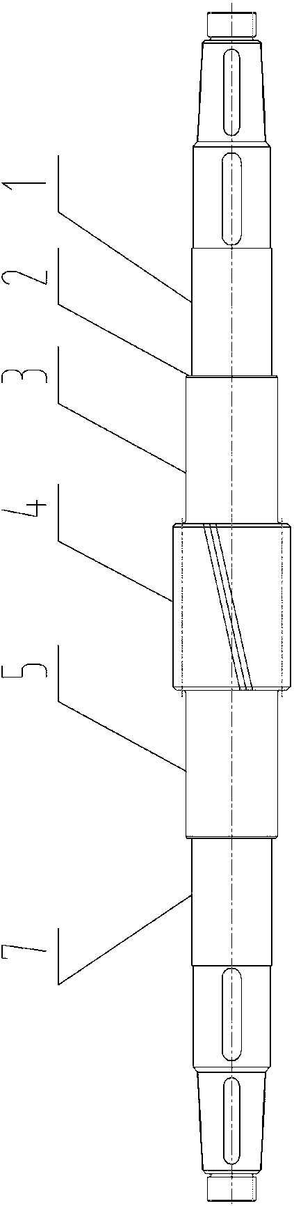
[0021] The structure of the gear shaft to be processed is as follows: figure 1 As shown: including a gear processing section 4 for processing gears, an upper stepped shaft structure 5 and a lower stepped shaft structure 1 are respectively arranged on the upper and lower sides of the gear processing section 4, and both the upper and side stepped shaft structures have The shaft shoulder 2 and the upper and lower sides of the gear processing section 4 on the gear shaft are respectively provided with an upper reference outer circle 7 and a lower reference outer circle 3 coaxial with the gear shaft.

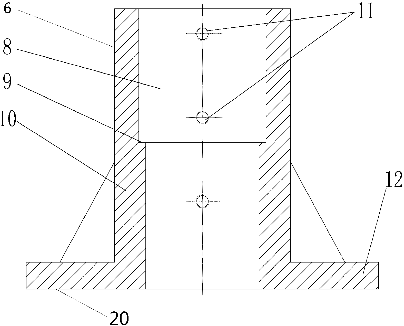
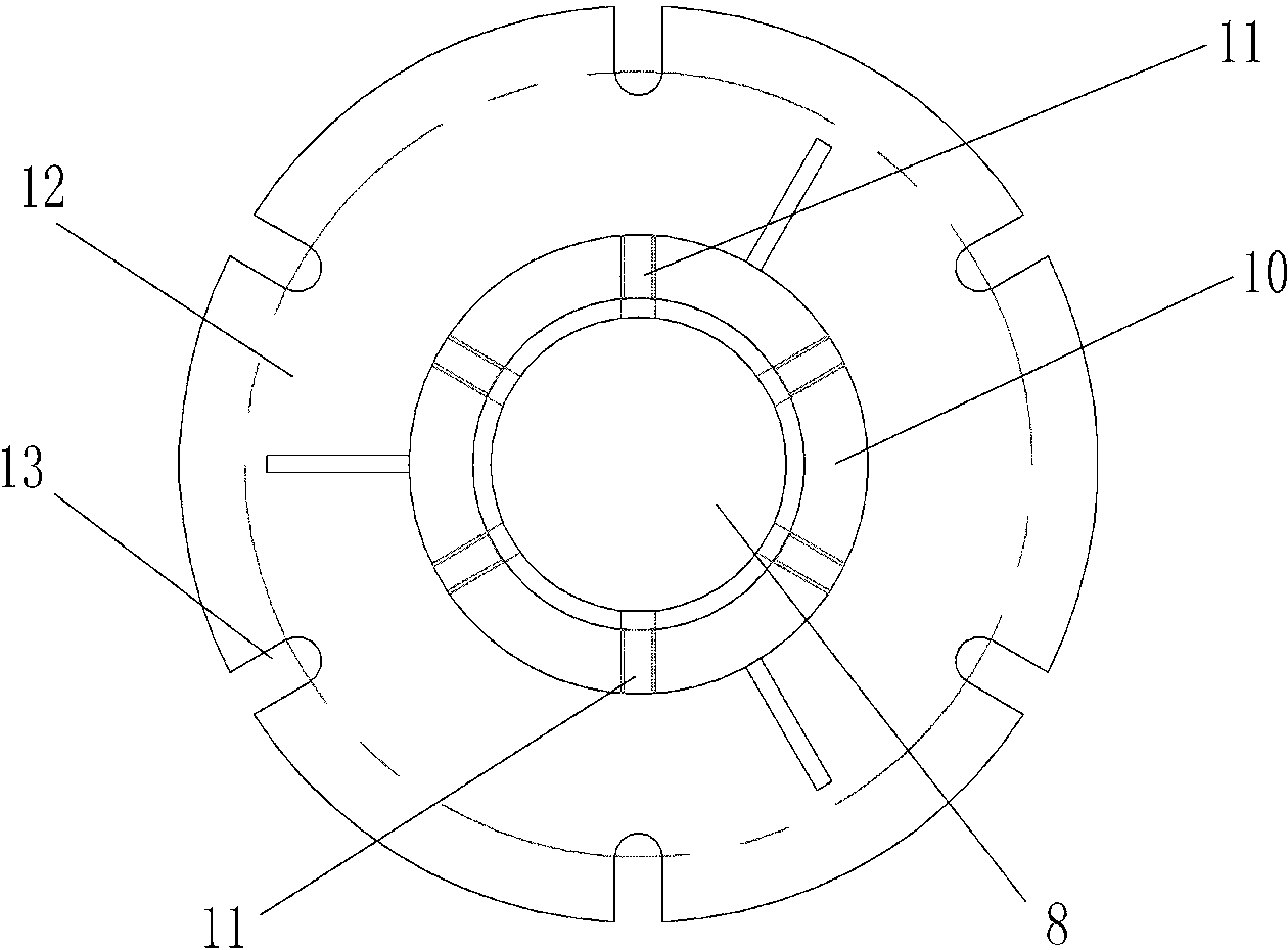
[0022] Examples of gear shaft clamping tooling Figure 1~4 As shown: it includes a stepped bushing with a body 10. The body 10 has a stepped hole 8 that runs through its upper and lower end surfaces. The stepped hole 8 is used for the lower side stepped shaft structure 1 of the corresponding gear shaft to be coaxial from top to bottom when in use. Adapted for insertion, the stepped h...


PUM


Abstract

The invention relates to a gear shaft machining method and a gear shaft clamping tool used in the method. The gear shaft machining method comprises the following steps: 1, installing a stepped shaft sleeve on a rotary worktable of a vertical gear hobber, and adjusting a stepped hole of the stepped shaft sleeve to be coaxial with the rotary worktable, wherein the diameter of an inner hole at the upper end of the stepped shaft sleeve is large, and the diameter of an inner hole at the lower end of the stepped shaft sleeve is small; 2, inserting a lower stepped shaft structure of a gear shaft to be machined into the stepped hole of the stepped shaft sleeve from top to bottom, and after adjusting the gear shaft to be coaxial with the stepped hole, locking the gear shaft on the stepped shaft sleeve by using the cooperation of at least two sets of threaded holes and corresponding locking bolts, wherein at least two sets of threaded holes are arranged on the stepped shaft sleeve in an up-and-down spaced setting mode; and 3, carrying out machining on a gear machining section of the gear shaft by using a gear hobbing head on the vertical gear hobber. The invention provides a gear shaft machining method through which the up-down moving stroke of the gear hobbing head on a corresponding stand column can be reduced.

Description

technical field [0001] The invention relates to a gear shaft machining method for machining a gear shaft by a vertical gear hobbing machine and a gear shaft clamping tool used in the method. Background technique [0002] Usually, horizontal hobbing machines are used to process batch gear shafts. However, because horizontal hobbing machines are relatively expensive, for single-piece, small-batch production of non-standard gear shafts, cheaper vertical hobbing machines are usually used in order to save costs. Machining of gear shafts. Existing vertical gear hobbing machines such as the "gear shaft processing fixture" disclosed in Chinese patent CN201702468U, the processing fixture includes a bed with a column, and a rotary table is arranged on the side of the column on the bed, and the column is on the side of the rotary table. One side is provided with a top coaxial with the rotary table through the outer bracket, and a height-increasing platform is provided between the colu...

Claims


Application Information

Patent Timeline
Patent Type & Authority Applications(China)
IPC IPC(8): B23F5/20B23F23/06
Inventor 郭莹峰闫建英代富贵张越恒
Owner 河南蒲瑞精密机械有限公司
Why Eureka
Try Eureka