Blade grinding clamp of silicon steel sheet punching die punch

A technology of punching die and silicon steel sheet, which is applied in the field of tooling and fixtures, can solve the problems of reducing the service life of punches, poor angle and alignment, and inconvenient adjustment of angles, so as to improve clamping efficiency, increase service life, and convenient effect

Active Publication Date: 2013-03-27
WUXI PUTIAN IRON CORE CO LTD
View PDF8 Cites 3 Cited by
  • Summary
  • Abstract
  • Description
  • Claims
  • Application Information

AI Technical Summary

Problems solved by technology

It is inconvenient to adjust the angle by using a vise to clamp the sharpening of the punch. If the angle and alignment are not good, the alloy of the punch will be wasted and the service life of the punch will be reduced.

Method used


Image

  • Blade grinding clamp of silicon steel sheet punching die punch
  • Blade grinding clamp of silicon steel sheet punching die punch
  • Blade grinding clamp of silicon steel sheet punching die punch

Examples


Embodiment Construction

[0017] The specific embodiments of the present invention will be further described below in conjunction with the accompanying drawings.

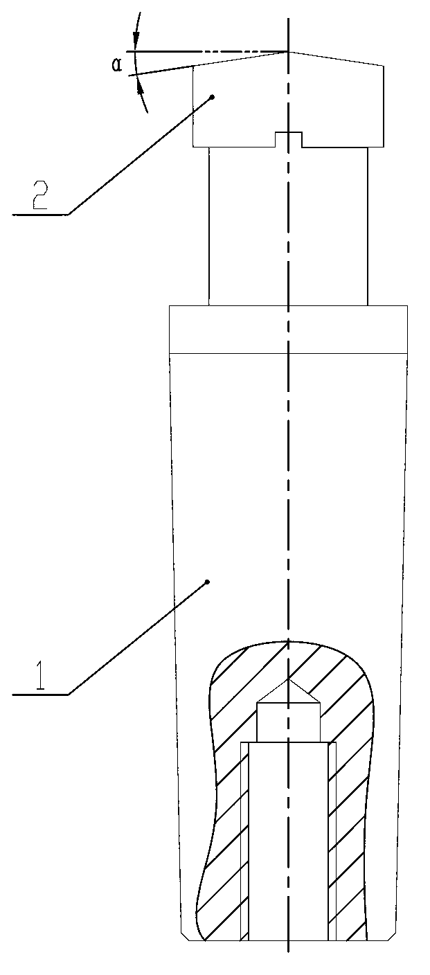
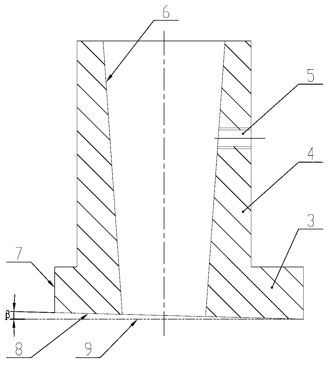
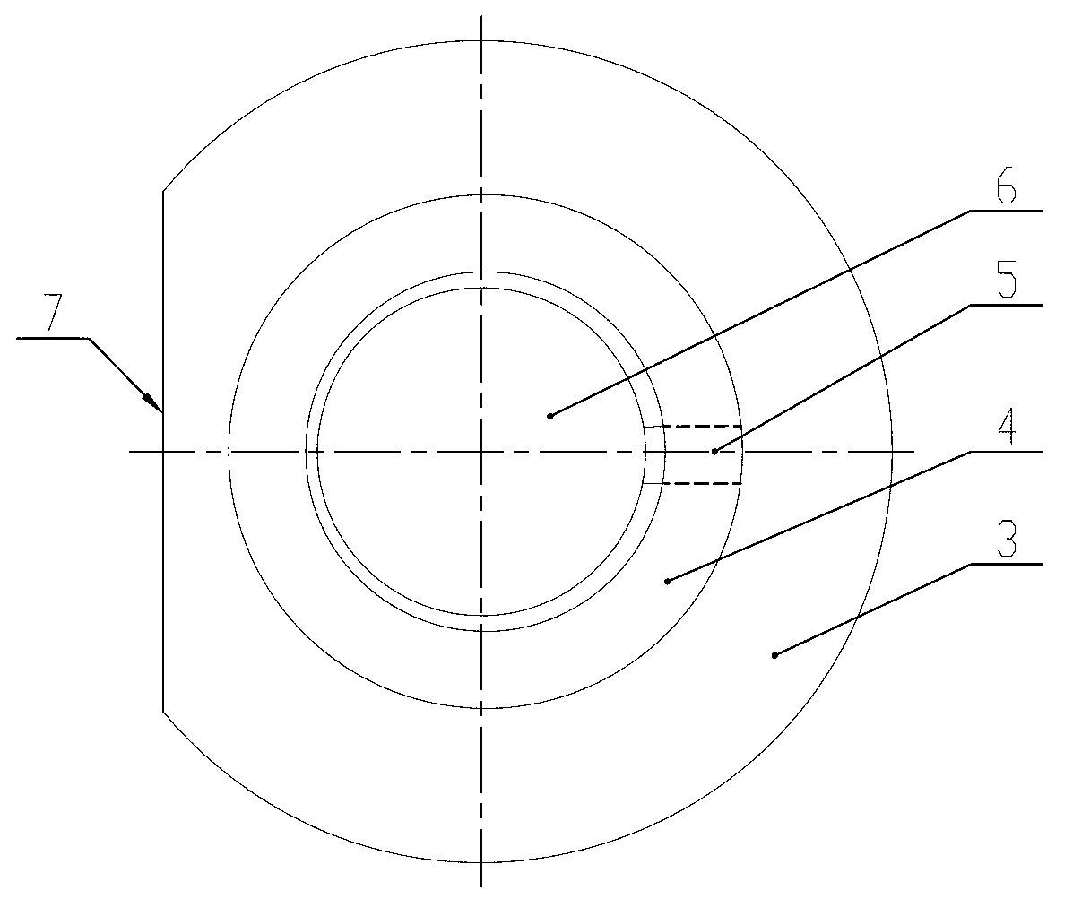
[0018] Figure 1 ~ Figure 3 Among them, including mold rod 1, punch 2, flange plate 3, clamp body 4, jacking screw 5, mold rod loading hole 6, centering plane 7, bottom surface 8, plane 9, etc.

[0019] like figure 1 Shown is a punch of a silicon steel sheet punching die, the punch 2 is fixed on the end of the die rod 1, and the die rod 1 is generally tapered. The end face of the punch 2 is a knife-edge shape formed by two symmetrical slopes, each slope forms a first angle α with a plane perpendicular to the axis of the die bar 1 . The first included angle α is generally 1.5°˜3°.

[0020] like figure 2 , image 3 As shown, it is a sharpening fixture for a silicon steel sheet punching die punch. The clamp includes an upright cylindrical clamp body 4, which is generally cylindrical. A mold rod loading hole 6 matching the mold rod 1 is ...


PUM


Abstract

The invention relates to a blade grinding clamp of a silicon steel sheet punching die punch. The punch is fixed at the end of a die rod. The end face of the punch is in a tool edge shape formed by two symmetrical inclined planes, and a first included angle is formed between each inclined plane and a plane perpendicular to the axial line of the die rod. The clamp comprises an upright cylindrical clamp body, wherein the clamp body is provided with a die rod mounting hole matched with the die rod, the clamp body is connected with a puller screw through a thread, the puller screw is communicated with the die rod mounting hole, a centering place parallel to the axial line of the die rod mounting hole is arranged on the side wall of the clamp body, the bottom face of the clamp body obliquely intersects with the axial line of the die rod mounting hole, a second included angle is formed between the bottom face of the clamp body and a plane perpendicular to the axial line of the die rod mounting hole, and the second included angle is equal to the first included angle. The blade grinding clamp of the silicon steel sheet punching die punch is convenient and rapid to clamp, improves blade grinding accuracy due to the fact that an angle is needless to be adjusted in blade grinding process, improves clamping efficiency due to convenient centering, can reduce unnecessary punch alloy grinding, and improves service life of the punch.

Description

technical field [0001] The invention relates to a tooling fixture in the production process of a transformer, in particular to a sharpening fixture for a silicon steel sheet punching die punch. Background technique [0002] During the stacking process of the transformer core, a large number of silicon steel sheets with holes are used, and some silicon steel sheets need to punch up to 4 holes, so the frequency of punching dies is quite high. [0003] The punching die includes a punch and a lower die. The structure of the punch is as figure 1 As shown, it includes the die bar 1 and the punch 2 fixed at one end of the die bar 1. The end face of the punch 2 is generally processed into two symmetrical inclined planes to form a knife-edge shape. The plane between each inclined plane and the plane perpendicular to the axis of the die bar 1 The angle between them is α. In order to reduce loss and reduce burr requirements, the punch must be sharp and durable, so frequent sharpenin...

Claims


Application Information

Patent Timeline
IPC IPC(8): B24B41/06
Inventor 蔡子祥李忠彬张聪
Owner WUXI PUTIAN IRON CORE CO LTD
Why Eureka
Try Eureka