
Pneumatic sling for dual-purpose full-function automatic grappling hook

A full-featured, spreader technology, applied in the direction of load hanging components, transportation and packaging, can solve the problems of automatic lifting, work accident of hooking hands and fingers, inability to use pneumatic spreader grab hooks, etc., to avoid manual hooking. Operation, the effect of reducing the incidence of industrial accidents and reducing costs

Active Publication Date: 2013-03-27
FUJIAN JIANHUA CONSTR MATERIALS CO LTD
View PDF11 Cites 8 Cited by
  • Summary
  • Abstract
  • Description
  • Claims
  • Application Information

AI Technical Summary

Problems solved by technology

The principle is to use the push of the cylinder to realize the opening and closing of the grabbing hooks in each grabbing wheel actuator, and when lifting heavy objects (heavy objects here usually refer to pipe molds in the pipe pile industry), each grabbing wheel actuator The middle grapple relies on the gravity of the pipe mold to realize self-locking, so as to complete the automatic lifting of the pipe mold. There is no running wheel position, so it is impossible to use the above-mentioned pneumatic lifting hook for automatic lifting (it should be noted that each complete pipe mold has a running wheel position, and the size of the running wheel position is relatively fixed, and the grapple depends on the tube Self-locking is achieved by combining the self-weight of the mold and the thrust of the cylinder), which can only be completed by the hook hand with the chain hook, which is very easy to cause work-related accidents to the fingers of the hook hand. More than 80% of the total industrial accidents of piles

Method used


Image

  • Pneumatic sling for dual-purpose full-function automatic grappling hook
  • Pneumatic sling for dual-purpose full-function automatic grappling hook
  • Pneumatic sling for dual-purpose full-function automatic grappling hook

Examples


Embodiment Construction

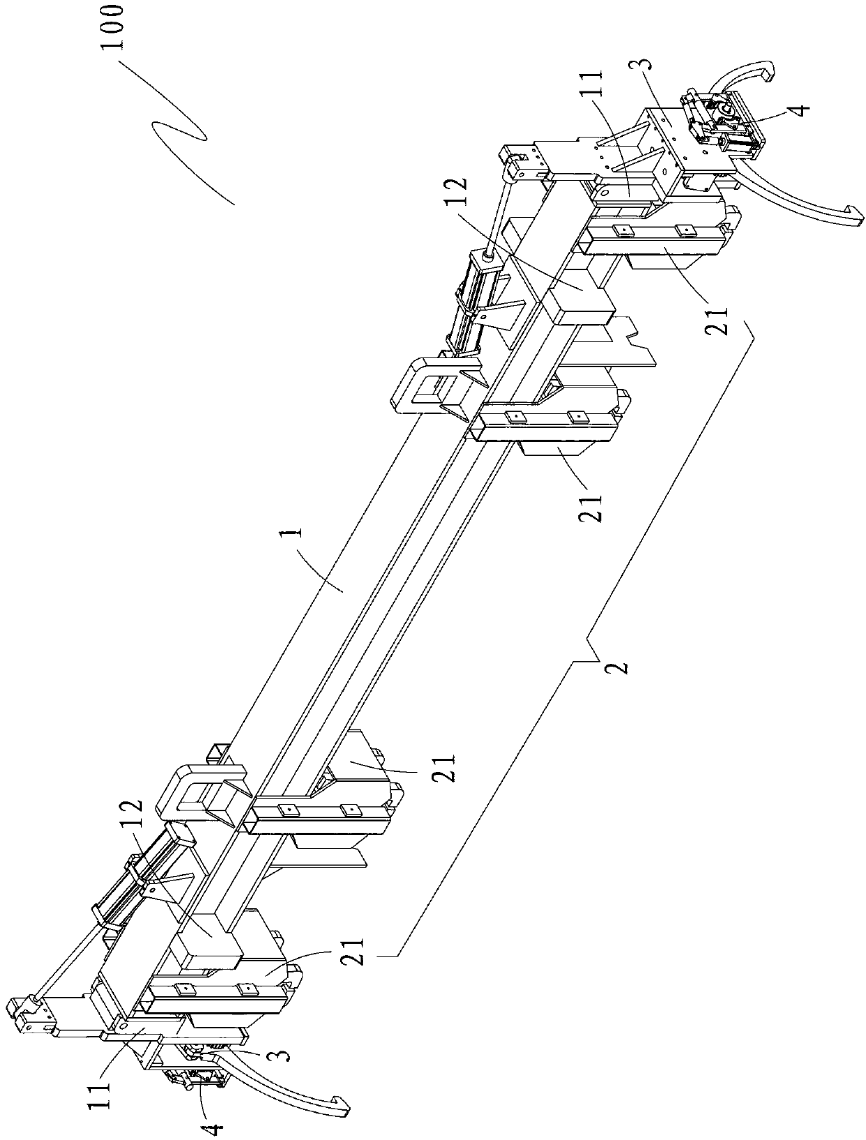
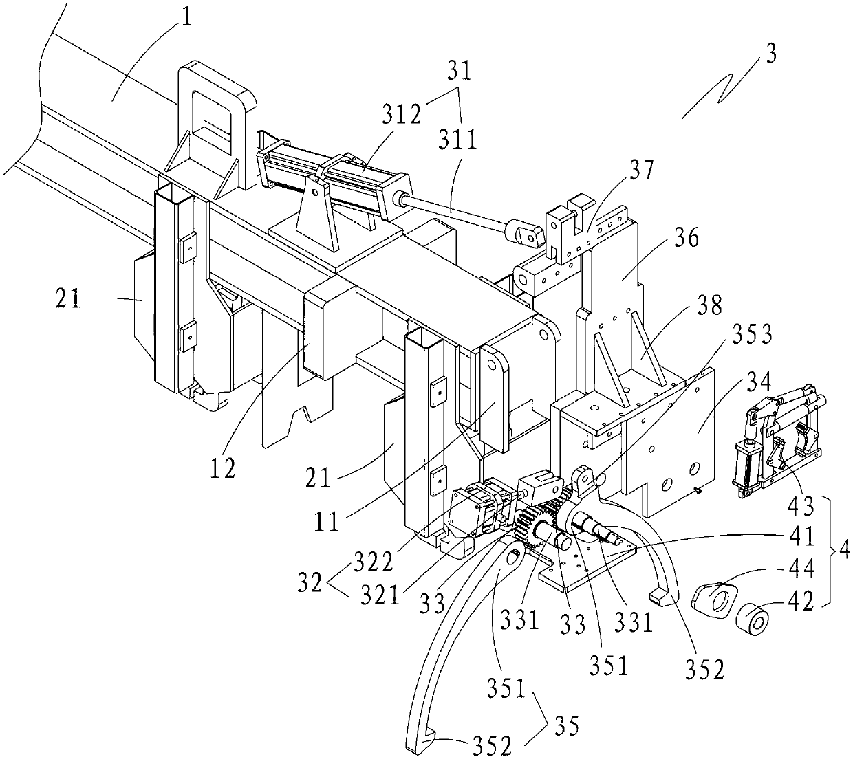
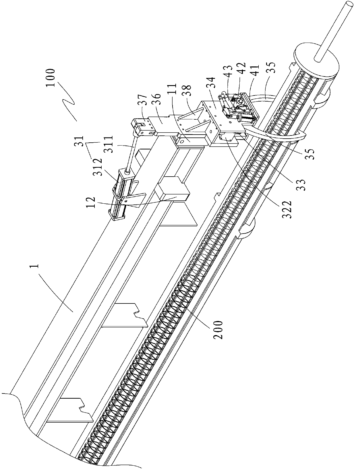
[0018] Please refer to figure 1 and figure 2 , the dual-purpose full-function automatic grab hook pneumatic spreader 100 of the present invention comprises a spreader main beam 1, a catch wheel system 2 made up of four catch wheel actuators 21, and one is used to control the entire pneumatic spreader 100 Provide a power source of compressed gas, and a control system, two hook-embracing bottom mold systems 3, and two safety brake mechanisms 4 respectively installed on the two hook-embracing bottom mold systems 3, each of the grabbing wheel actuators 21 Both are fixed on the main beam 1 of the spreader and connected with the power source and the control mechanism. The two hook-embracing bottom mold systems 3 are respectively connected to the two ends of the spreader main beam 1; each of the hook-embracing bottom mold systems 3 includes A first air cylinder 31, a second air cylinder 32, two intermeshing belt shaft gears 33, a gear box 34 for accommodating the two belt shaft gea...


PUM


Abstract

The invention provides a pneumatic sling for a dual-purpose full-function automatic grappling hook. The pneumatic sling comprises a sling main beam, a grappling wheel system consisting of four grappling wheel actuating mechanisms, a power source, a control system, two hooking bottom mold systems and two safety brake mechanisms which are respectively arranged on the two hooking bottom mold systems, wherein the two hooking bottom mold systems are respectively connected to two ends of the sling main beam; each hooking bottom mold system comprises a first cylinder arranged on the upper surface of the sling main beam, a second cylinder, two gears with shafts which are meshed with each other, a gearbox used for accommodating the two gears with shafts, and two clamping claws; and each safety brake mechanism comprises a brake fixing plate, a brake hub and a brake rack used for braking the gears with shafts. The pneumatic sling has the advantages that a complete pipe die can be automatically lifted, and a half of pipe die is automatically lifted, so that the industrial accident rate of hooking hands in the pipe pile industry is greatly reduced.

Description

【Technical field】 [0001] The invention relates to a crane spreader for mechanical heavy industry, in particular to a dual-purpose full-function automatic grabbing hook pneumatic spreader. 【Background technique】 [0002] The spreader is an integral part of the heavy industry crane equipment. If the heavy industry crane equipment is a human body, then the spreader is equivalent to the hands of the human body. The most widely used in the existing spreader is the pneumatic spreader. [0003] In the pipe pile industry, most of the pneumatic spreaders currently used include the main beam of the spreader, the grabbing wheel system composed of four grabbing wheel actuators, the power source for providing compressed gas, and the control mechanism. The actuators of the catch wheel are fixed on the main beam of the spreader and connected with the power source and the control mechanism. The principle is to use the push of the cylinder to realize the opening and closing of the grabbing...

Claims


Application Information

Patent Timeline
IPC IPC(8): B66C1/28
Inventor 陈川闻柯卢铿江海涛
Owner FUJIAN JIANHUA CONSTR MATERIALS CO LTD
Learn More