Automatic spool welding machine

An automatic welding machine and I-shaped wheel technology, applied in welding equipment, auxiliary welding equipment, welding/cutting auxiliary equipment, etc., can solve the problem of high labor intensity of the inner tube of the I-shaped wheel, uneven position of welding points, and poor quality. Guarantee and other issues, to avoid the need for manual overturning operation, to avoid uneven spot welding, and to achieve the effect of high production efficiency

Active Publication Date: 2015-12-30
ZHANGJIAGANG DONGHANG MACHINERY
View PDF5 Cites 8 Cited by
  • Summary
  • Abstract
  • Description
  • Claims
  • Application Information

AI Technical Summary

Problems solved by technology

[0003] The purpose of the present invention is to overcome the defects in the prior art of welding the inner tube of the I-shaped wheel, such as high labor intensity, uneven welding spot position and unguaranteed quality, and provide an I-shaped wheel welding machine that can automatically lift and turn over

Method used


Image

  • Automatic spool welding machine

Examples


Embodiment Construction

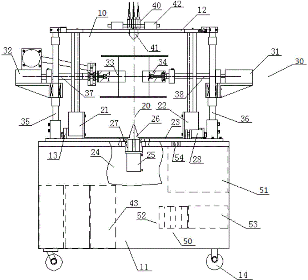
[0013] Such as figure 1 As shown, a kind of I-wheel automatic welding machine includes a mounting frame 10, a lifting device 20, a turning device 30, a welding machine 40 and a control mechanism 50, and the mounting frame 10 includes a base 11, an upper mounting plate 12, a lower mounting plate 13 and the wheels 14 arranged at the bottom of the base 11, the lower mounting plate 13 is arranged on the base 11, the welding machine 40 is arranged on the upper mounting plate 12, the lower end of the welding machine 40 is provided with an upper positioning top 41, and the welding machine 40 There are welding gun clamping devices 42 on both sides, the welding machine box 43 of the welding machine 40 is arranged inside the base 11, and the lifting device 20 and the flipping device 30 are respectively arranged in the middle of the upper mounting plate 12 and the lower mounting plate 13 , the control mechanism 50 is disposed inside the base 11 . Described elevating device 20 comprises ...


PUM


Abstract

The invention relates to an automatic spool welding machine. The automatic spool welding machine comprises an installation frame, a lifting device, a turning device, a box body machine frame, a control mechanism and a welding machine body. The installation frame comprises a base, an upper installation plate and a lower installation plate. The welding machine body is arranged on the upper installation plate. The lifting device comprises a first rodless cylinder and a second rodless cylinder which are arranged on the lower installation plate, a lifting connection supporting plate and a box body machine frame. The lifting connection supporting plate and the box body machine frame are connected to and arranged on the two sides in the first rodless cylinder and the second rodless cylinder. The turning device comprises a double-rod cylinder, a rotation cylinder clamping and turning mechanism, a turning mechanism, a first slide rod and a second slide rod. The first slide rod and the second slide rod are fixed to the two ends of the base. The rotation cylinder is arranged on the first slide rod and connected with the clamping and turning mechanism through a first connection rod. The double-rod cylinder is arranged on the second slide rod and connected with the turning mechanism through a second connection rod. The lifting device and the turning device are controlled through the control mechanism, and therefore spools are automatically welded, and the automatic spool welding machine has the advantages of being high in production efficiency and stable in quality.

Description

technical field [0001] The invention relates to a welding machine, in particular to an automatic I-shaped wheel welding machine. Background technique [0002] At present, the use of I-shaped wheels is more and more widely used. Generally, I-shaped wheels are used to wind metal wires or steel wire ropes. When processing I-shaped wheels, manual welding is generally used, and the labor intensity is very high. Moreover, during processing, due to the need to The seams and both sides of the inner tube of the I-shaped wheel are welded along the circumferential direction, so the spot welding position of the inner tube of the I-shaped wheel is not uniform during the whole welding process, which will lead to irregular solder joints, and the welding of the I-shaped wheel During the process of the two sides of the wheel along the circumferential direction, it is necessary to adjust the position many times to weld it. In this way, not only the welding time is long, the labor intensity is...

Claims


Application Information

Patent Timeline
Patent Type & Authority Applications(China)
IPC IPC(8): B23K37/00B23K37/047
CPCB23K37/00B23K37/047
Inventor 顾建东
Owner ZHANGJIAGANG DONGHANG MACHINERY
Why Eureka
Try Eureka