Drain pump

A drainage pump and outlet technology, applied in the direction of pumps, pump components, pump devices, etc., can solve the problems of easy water entry, drainage pump noise, and increased vibration, so as to suppress vibration and noise, reduce vibration and noise, and reduce noise. Sex-enhancing effect

Active Publication Date: 2013-03-27
FUJIKOKI MFG CO LTD
View PDF5 Cites 7 Cited by
  • Summary
  • Abstract
  • Description
  • Claims
  • Application Information

AI Technical Summary

Problems solved by technology

In order to avoid the drop of the discharge capacity, it is conceivable to reduce the height of the annular wall member 64, but in this case, there is such a problem that water easily enters the space between the blades on the rear side in the direction of rotation, and the noise and vibration of the drain pump get bigger

Method used


Image

  • Drain pump
  • Drain pump
  • Drain pump

Examples


no. 1 Embodiment

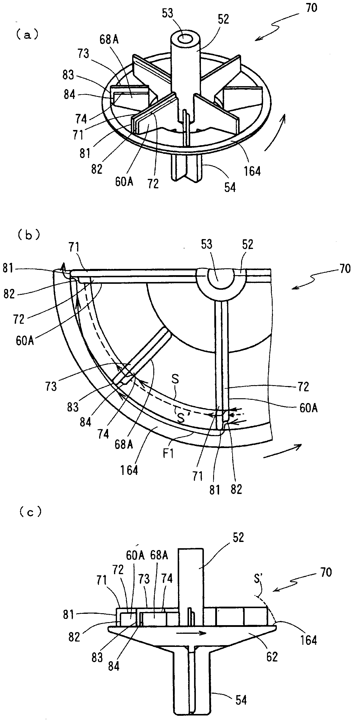
[0063] figure 1 It is a figure which shows an example of the rotary vane used for the drainage pump of this invention, figure 1 (a) is a perspective view showing the whole rotating blade, figure 1 (b) is to figure 1 A top view of a partially enlarged representation of the rotating blade shown in (a), figure 1 (c) is figure 1 (a) Front view of the rotating blade shown. In the description of the embodiment of the present invention, for the Figure 17 shown in previous rotary blades and Figure 4 Common configurations of the rotating blades of the comparative example shown are denoted by the same reference numerals, and detailed description thereof will be omitted. In addition, symbols 60A and 68A are given to the large-diameter blades and the auxiliary blades of the rotary blade 70 in this embodiment.

[0064] exist figure 1 In the rotary vane 70 of the shown drain pump, a stepped portion 72 is provided on the upper edge portion 71 of the edges of the large-diamete...

no. 2 Embodiment

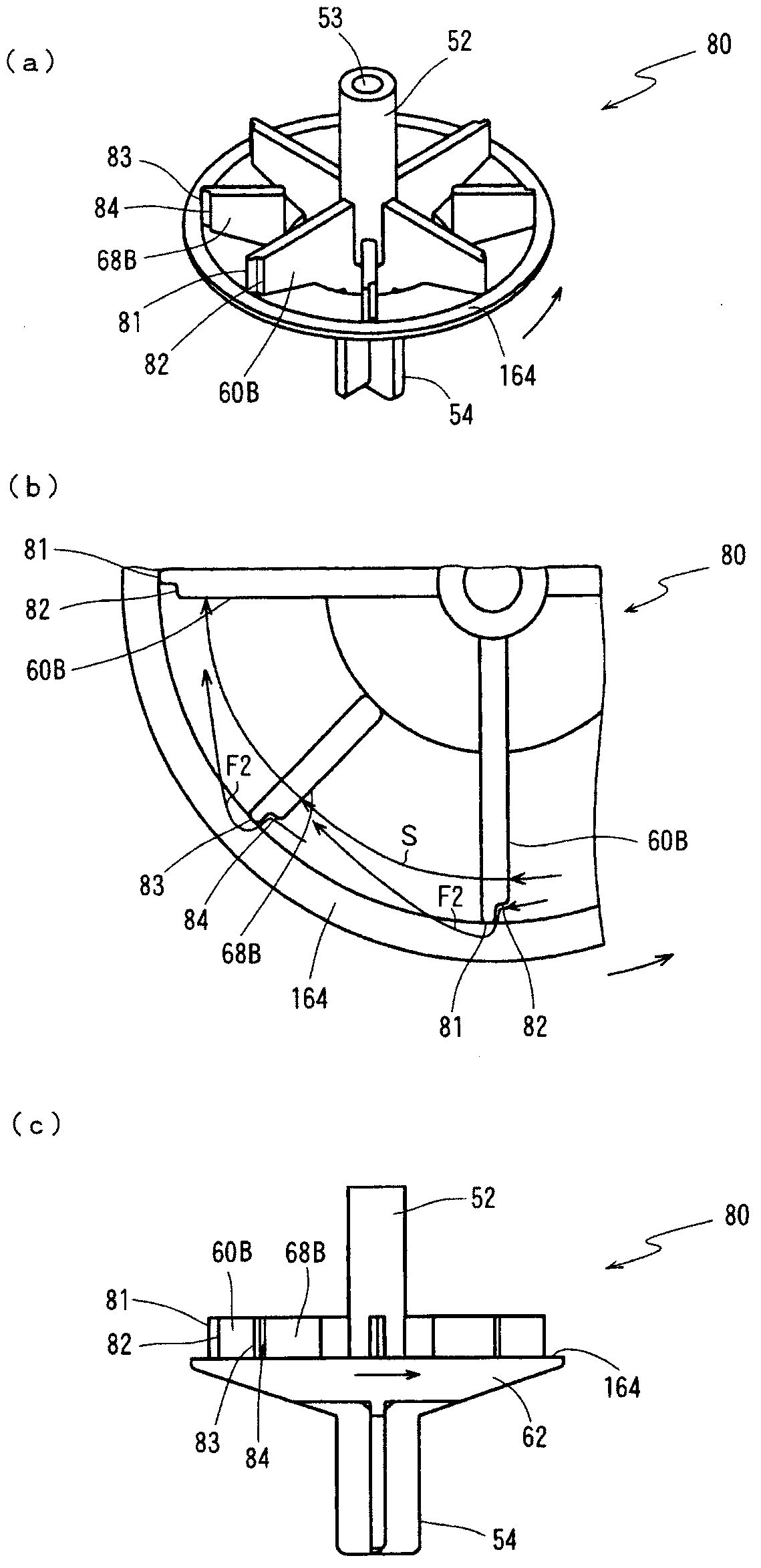
[0067] figure 2 It is a figure which shows another example of the rotary vane used for the drainage pump of this invention, figure 2 (a) is a perspective view showing the whole rotating blade, figure 2 (b) is to figure 2 A top view of a partially enlarged representation of the rotating blade shown in (a), figure 2 (c) is figure 2 (a) Front view of the rotating blade shown. In addition, reference numerals 60B and 68B are attached to the large-diameter blade and the auxiliary blade of the rotary blade 80 of this embodiment.

[0068] exist figure 2 In the rotary vane 80 of the illustrated drain pump, a stepped portion 82 is provided only on the outer edge portion 81 of the edge portion of the large-diameter vane 60B. In addition, the outer edge portion 83 of the auxiliary blade 68B is also provided with a stepped portion 84 . The stepped portions 82 , 84 are formed over the entire lengths of the outer edge portions 81 , 83 of the blades 60B, 68B. The stepped portio...

no. 3 Embodiment

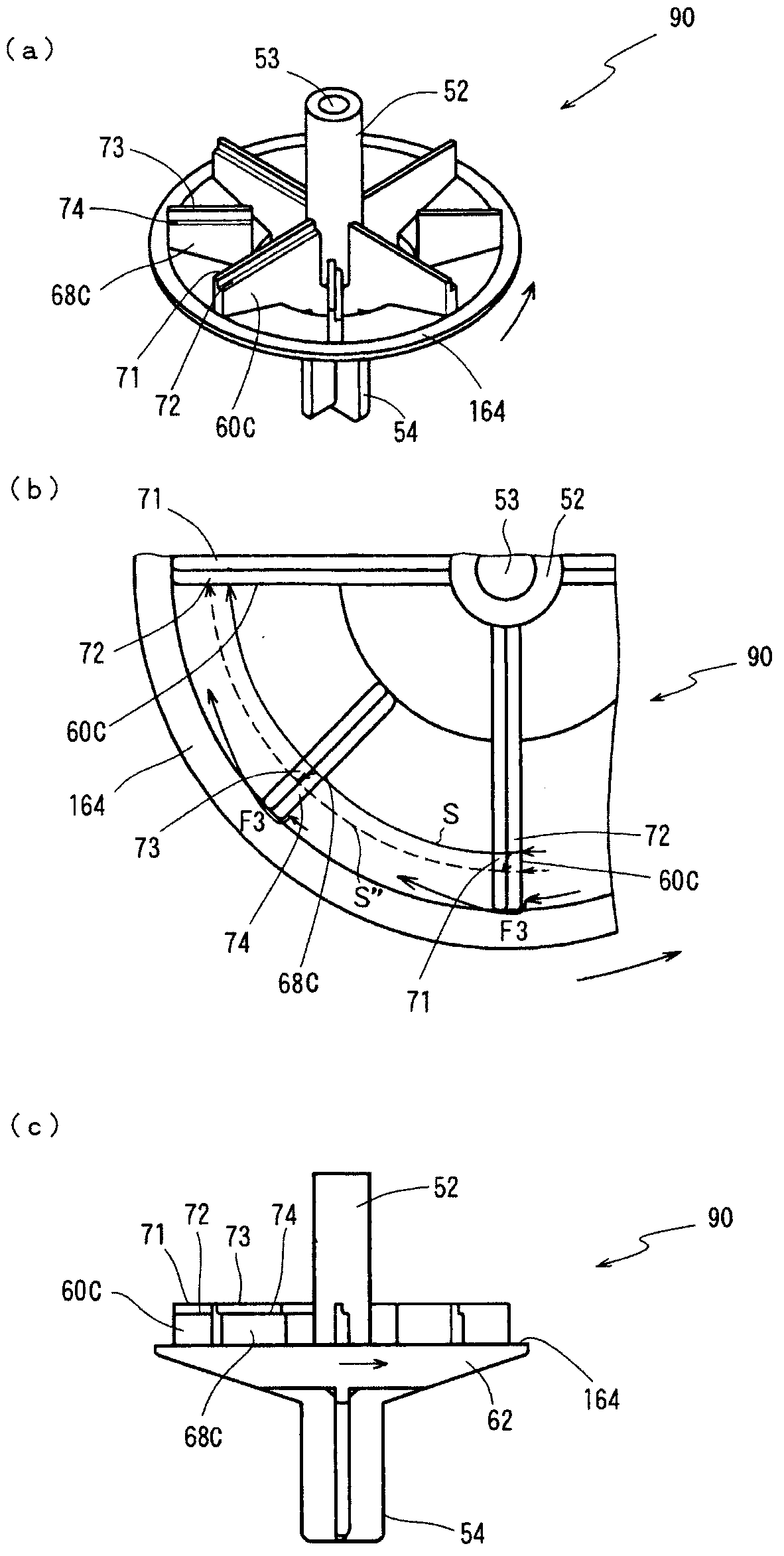
[0070] image 3 It is a figure which shows the 3rd embodiment of the rotating vane used for the drainage pump of this invention, image 3 (a) is a perspective view showing the whole rotating blade, image 3 (b) is to image 3 A top view of a partially enlarged representation of the rotating blade shown in (a), image 3 (c) is image 3 (a) Front view of the rotating blade shown. In addition, symbols 60C and 68C are assigned to the large-diameter blades and auxiliary blades of the rotary blade 90 in this embodiment.

[0071] image 3 In the rotary vane 90 of the illustrated drain pump, the upper edge portion 71 of the edge portion of the large-diameter vane 60C is provided with a stepped portion 72 . In addition, a stepped portion 74 is also provided on the upper edge portion 73 of the auxiliary blade 68C. The stepped portions 72, 74 are formed over the entire lengths of the upper end edge portions 71, 73 of the blades 60C, 68C. The steps 72 and 74 function to splash the...


PUM


Abstract

Provided is a drain pump. Rotating blades (70) adopted by the drain pump comprise multiple plate-shaped large-diameter blades (60), which are extended towards the radial direction from a shaft part (52) in connection with an output shaft of an electric motor; multiple plate-shaped small-diameter blades (54), which are connected with lower edge parts of the large-diameter blades (60); and auxiliary blades (68) between the adjacent large-diameter blades (60). Step parts (72, 74, 82 and 84) are arranged at the peripheries of the large-diameter blades and the auxiliary blades to guide the water that is stirred by the blades to the outer sides of the blades. By means of the step parts, the space into which the drain water flows behind the blades is suppressed. In this way, the discharge ability is improved, while vibration and noise are suppressed. By the drain pump of the invention, improvement of the discharge ability and the mute property during operation can be realized at the same time.

Description

technical field [0001] The invention relates to a drainage pump for discharging the drainage water in the drainage pan receiving the water condensed by the indoor heat exchanger of the air conditioner. Background technique [0002] Conventionally, an air conditioner of a type buried in an indoor ceiling is equipped with a drain pan for receiving drain water condensed on the surface of an indoor heat exchanger of the air conditioner. A drain pump (drain pump) is used to discharge the drain water in the drain pan to the outside. [0003] Figure 17 An example of a drain pump used in an air conditioner is shown. exist Figure 17 middle, Figure 17 (a) is a front view showing a partial section of the drainage pump, Figure 17 (b) is Figure 17 (a) is a top view of an example of a rotary vane used in a drainage pump, Figure 17 (c) is Figure 17 (b) is a front view of a rotary blade (see Patent Document 1). [0004] The overall drain pump denoted by reference numeral 1 includes...

Claims


Application Information

Patent Timeline
Patent Type & Authority Applications(China)
IPC IPC(8): F04D13/06F04D29/24
CPCF04D1/14F04D13/08F04D29/18
Inventor 佐藤克司佐藤永加藤友也山开健治
Owner FUJIKOKI MFG CO LTD
Why Eureka
Try Eureka