Connector detecting device and connector detecting method

A detection device and detection method technology, applied in the direction of measuring devices, instruments, measuring electricity, etc., can solve the problems of increasing contact impedance, not having too much influence on the circuit, temperature rise, etc., and achieve the effect of ensuring safety

Active Publication Date: 2013-03-27
GUANGDONG OPPO MOBILE TELECOMM CORP LTD
View PDF5 Cites 8 Cited by
  • Summary
  • Abstract
  • Description
  • Claims
  • Application Information

AI Technical Summary

Problems solved by technology

The material of the interface on the above-mentioned mobile phone is usually metal copper foil, and there are various forms such as thimble and shrapnel in form. The connection of these interfaces has a certain contact resistance, generally ranging from several milliohms to tens of milliohms, but If there are some abnormalities, such as dirty contact points, the contact resistance will be greatly increased, making the contact resistance reach more than 100 milliohms
[0003] Under normal circumstances, when the current is less than 1A, the above-mentioned poor contact is allowed. Taking 100 milliohms as an example, the voltage drop is 0.1V, and the heat generation is only 0.1W, which does not have much impact on the circuit; and for those who need Through a high-current connector, for example, through a 10A current, even if there is only a contact resistance of 20 milliohms, it will generate 2W of heat. Once the heat cannot be removed in time, it will cause the temperature to rise and burn the connector.
[0004] For the above-mentioned connectors that need to pass through a large current, in the current use, the contact status has not been detected in real time. Therefore, once there is a bad contact, if the user continues to use it without knowing it, it will seriously heat up and burn the connection. connector, shortening the service life of the connector

Method used


Image

  • Connector detecting device and connector detecting method
  • Connector detecting device and connector detecting method
  • Connector detecting device and connector detecting method

Examples


Embodiment Construction

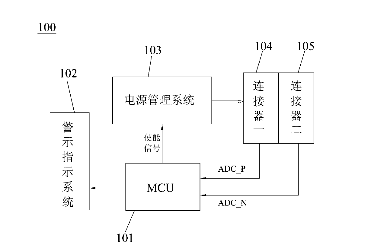
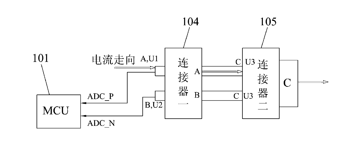
[0027] Embodiments of the present invention will now be described with reference to the drawings, in which like reference numerals represent like elements. The connector detection device 100 of the present invention is used for real-time detection of the contact status of the connector passing through the high current, to determine whether the connection of the connector is normal, and to determine whether to output a high current, thereby preventing the connector from being damaged due to excessive heat. burn out. Wherein, the "connector" generally refers to all connectors of the mobile communication terminal that pass through a large current, for example, the "connector" can be a battery connector in a mobile phone, or a USB connector of an adapter, etc. Certainly not limited thereto, this is a technology well known to those skilled in the art.

[0028] Such as figure 1 , figure 2 As shown, the connector detection device 100 of the present invention includes a controller...


PUM


Abstract

The invention discloses a connector detecting device. The connector detecting device comprises a controller, a power supply managing system, a warning indication system, a first connector and a second connector. The power supply managing system and the warning indication system are respectively connected with the controller, the first connector is connected with the second connector through a difference detecting line ADC P, the second connector is connected with the controller through a difference detecting line ADC N, and the power supply managing system is electrically connected with the first connector. Therefore, contact resistance between the connectors can be indirectly detected by detecting pressure difference between the difference detecting line ADC P and the difference detecting line ADC N, accordingly abnormal contact of the connectors in the using process can be ensured to be detected, the connectors are protected and prevented from being burned out due to poor contact in the frequent using process, and safety of large-current connectors is ensured. In addition, the invention further discloses a connector detecting method. The connector detecting method has same effect.

Description

technical field [0001] The invention relates to a detection device for a connector, in particular to a detection device and a detection method for detecting the contact state of a connector passing through a high current. Background technique [0002] With the development of mobile communication technology and the increase of user demands, various portable mobile communication terminals (such as mobile phones, tablet computers, etc.) are becoming more and more popular. Taking a mobile phone as an example, due to structural limitations or functional requirements when designing a mobile phone, it is necessary to have some interfaces that pass through a large current (such as battery interfaces, charging interfaces, etc.), and these interfaces need to pass through a large current. Forms a connector through which high current flows. The material of the interface on the above-mentioned mobile phone is usually metal copper foil, and there are various forms such as thimble and shr...

Claims


Application Information

Patent Timeline
Patent Type & Authority Applications(China)
IPC IPC(8): G01R31/04
Inventor 张加亮吴克伟
Owner GUANGDONG OPPO MOBILE TELECOMM CORP LTD
Why Eureka
Try Eureka