Permanent-magnet pulse contactor

A technology of contactors and permanent magnets, applied in the direction of non-polar relays, etc., can solve the problems of power consumption, slow opening speed, contactor failure, etc., to reduce production costs and use costs, increase use capacity, and not easily damage the contactor head effect

Inactive Publication Date: 2005-01-12
吕炎
View PDF0 Cites 7 Cited by
  • Summary
  • Abstract
  • Description
  • Claims
  • Application Information

AI Technical Summary

Problems solved by technology

When the contactor is working, it not only needs to maintain the current and consume electric energy, but also the current will cause the electromagnetic coil to heat up, which will burn out the electromagnetic coil and cause the contactor to fail, and maintaining the current will generate noise and affect the working environment
Once the power supply voltage disappears or decreases significantly, so that the electromagnetic coil is not excited or the excitation is insufficient, the moving iron core will be released under the elastic force of the reaction spring due to the disappearance or too small electromagnetic attraction force, so that the moving and static contacts are disconnected, but they are just separated. Slow speed, poor arc breaking ability, easy to damage the contacts, thus shortening the service life of the contacts
If you want to increase the spring reaction force to improve the arc extinguishing ability, you must increase the maintenance current, which will inevitably increase energy consumption, increase the amount of raw materials, and increase production costs and operating costs.
In addition, the core magnetic density of the contactor should not be too high, generally up to 7600 gauss, so the pressure of the contact pressure spring should not be too high, so the contact resistance of the contact is relatively large, which affects the use capacity of the contactor

Method used


Image

  • Permanent-magnet pulse contactor
  • Permanent-magnet pulse contactor
  • Permanent-magnet pulse contactor

Examples


Embodiment Construction

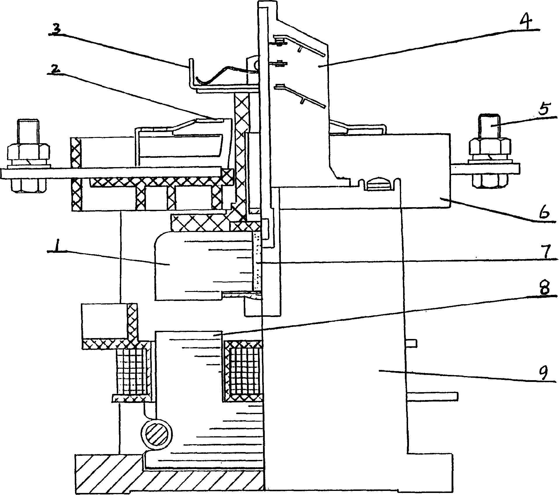
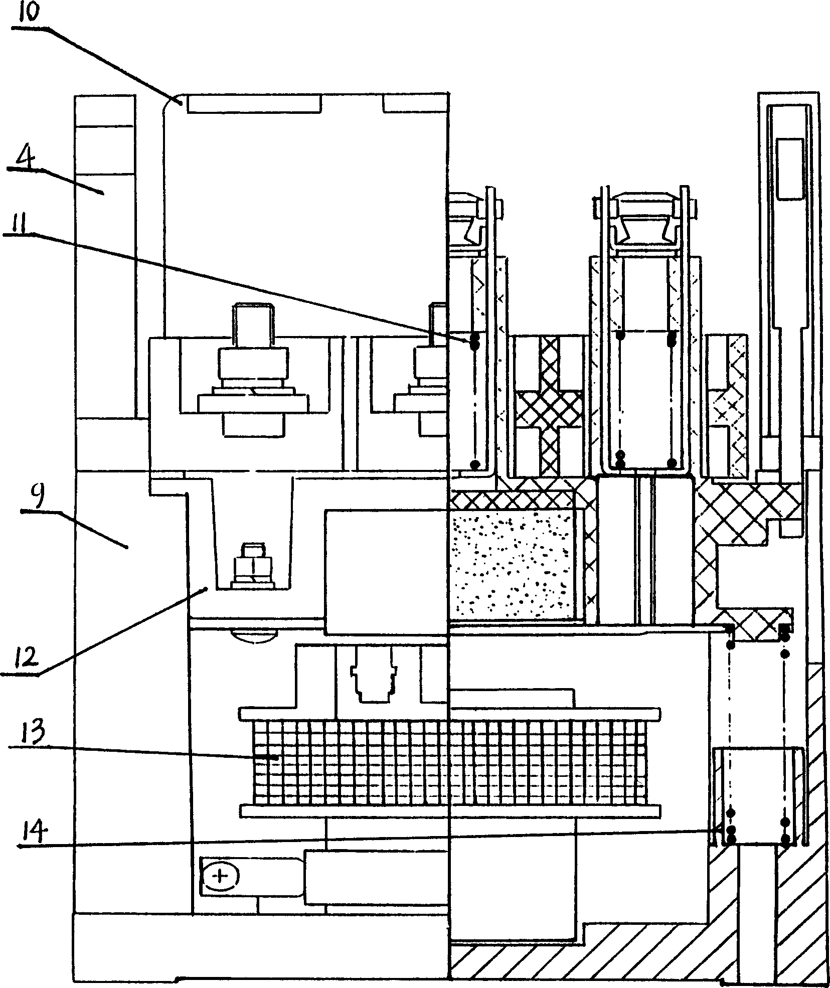
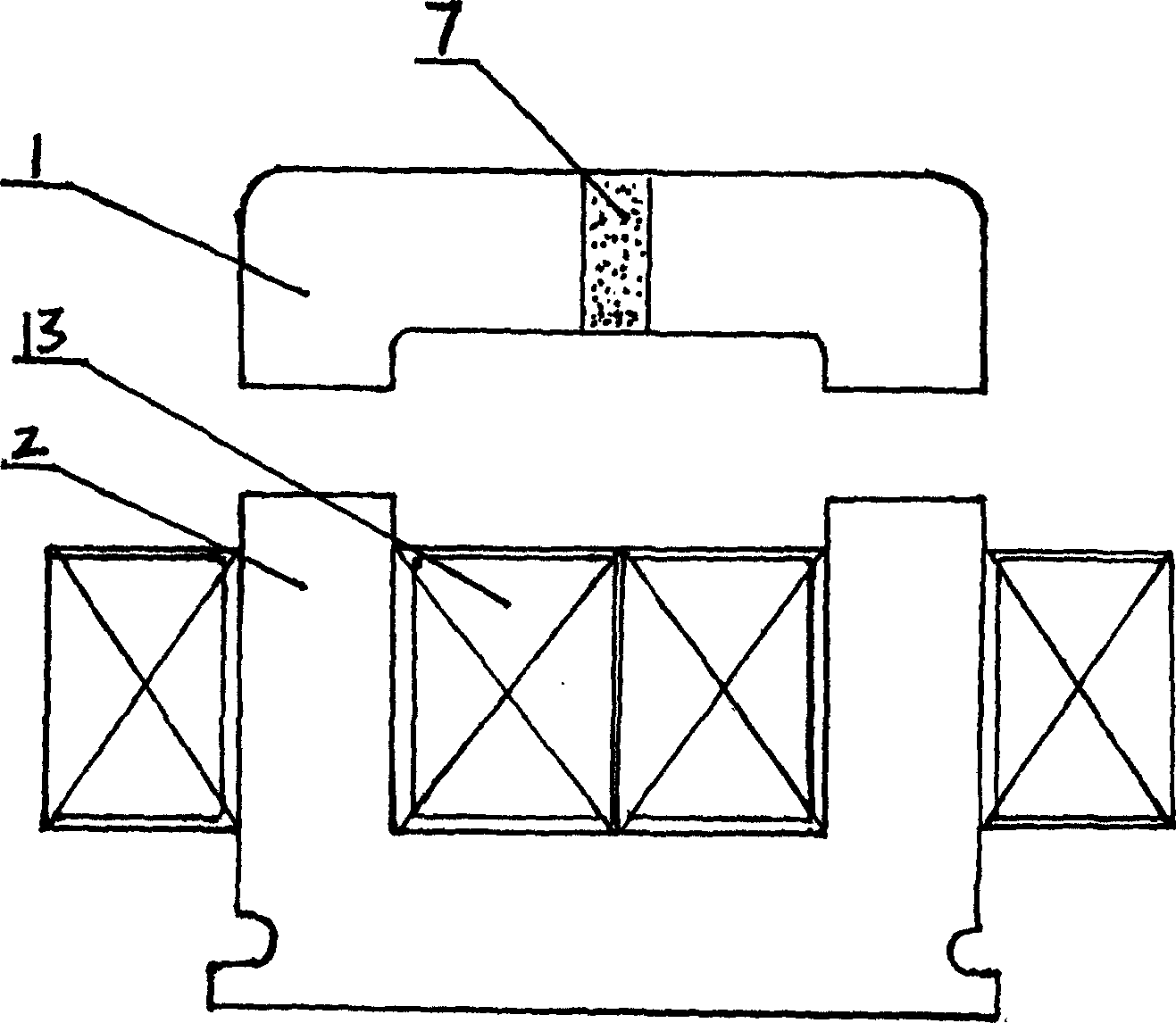
[0014] As shown in the figure, the static iron core 8 is fixedly connected to the bottom of the housing 9 and cooperates with the electromagnetic coil 13 , and the upper part of the static iron core 8 is provided with a corresponding moving iron core 1 . The permanent magnetic steel 7 is arranged on the moving iron core 1, and is fixedly connected with the moving bracket 12. Due to the structure of the permanent magnetic steel 7, the contactor does not need to maintain the current after it is turned on, and the static iron core 8 can adopt a non-split phase iron core without split phase and short-circuit ring, which still makes the moving iron core 1 stable and does not vibrate when it is pulled in. , which simplifies the core structure and reduces the product cost. Main springs 14 are arranged on both sides below the movable support 12, and a contact fixing plate 6 is arranged above. Wiring fixing screws 5 are arranged on both sides of the contact fixing plate 6, and are con...


PUM


Abstract

The contactor includes case, quenching pot, electromagnetism gear inside case. The electromagnetism gear is composed of dynamic iron core, static iron core and magnet coil. Contact gear including dynamic contact, static contact and assistant contact is above the case. Characters are that magnet steel of permanent magnetism is setup on dynamic iron core. impulse current in 0.2 second completes function of contactor without consuming maintenance current so as to save energy more than 99%. Features of the disclosed contactor are: no heat generation from electromagnetism coil, quick detaching contacts, strong arc extinguishing capability, small contact resistance and 12000 gauss high magnetism density.

Description

technical field [0001] The invention belongs to the field of electromechanical technology, in particular to a permanent magnet pulse contactor. Background technique [0002] The contactor is an automatic control electrical appliance, which can be used to frequently connect or disconnect large-capacity AC and DC load circuits at long distances. Contactors can be divided into DC and AC contactors according to the type of current passed through the main contacts. At present, most of the control circuits use AC contactors. When the contactor is working, it not only needs to maintain the current and consume electric energy, but also the current will cause the electromagnetic coil to heat up, which will burn out the electromagnetic coil and cause the contactor to fail, and maintaining the current will generate noise and affect the working environment. Once the power supply voltage disappears or decreases significantly, so that the electromagnetic coil i...

Claims


Application Information

Patent Timeline
Patent Type & Authority Applications(China)
IPC IPC(8): H01H51/01
Inventor 吕炎
Owner 吕炎
Why Eureka
Try Eureka