Hydraulic gas buffer device and gas tank with same

A technology of gas buffering and gas holders, applied in the field of gas holders, which can solve the problems of not considering the buffer device of the piston at the bottom, damage of the gas holder piston, etc., and achieve the effects of simple composition, increased effective stroke, and low cost

Pending Publication Date: 2021-01-05
CISDI RES & DEV CO LTD
View PDF0 Cites 0 Cited by
  • Summary
  • Abstract
  • Description
  • Claims
  • Application Information

AI Technical Summary

Problems solved by technology

[0007] At present, no matter what kind of gas cabinet is used, the piston bottoming buffer device is not considered at the lower part of the piston or the piston bottom support of the gas cabinet. If the piston falls directly to the bottom at the normal operating speed, the piston may completely fall due to impact with the bottom. Damaged gas tank piston

Method used


Image

  • Hydraulic gas buffer device and gas tank with same
  • Hydraulic gas buffer device and gas tank with same
  • Hydraulic gas buffer device and gas tank with same

Examples


Embodiment Construction

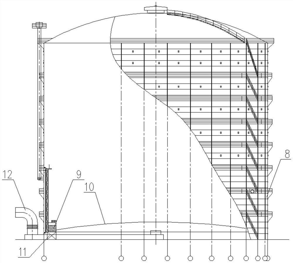
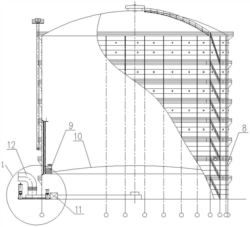
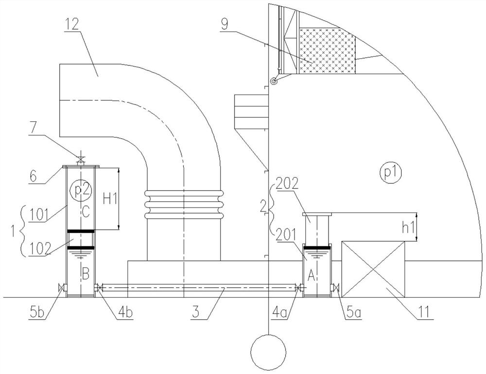
[0035] Embodiments of the present invention are described below through specific examples, and those skilled in the art can easily understand other advantages and effects of the present invention from the content disclosed in this specification. The present invention can also be implemented or applied through other different specific implementation modes, and various modifications or changes can be made to the details in this specification based on different viewpoints and applications without departing from the spirit of the present invention. It should be noted that the diagrams provided in the following embodiments are only schematically illustrating the basic concept of the present invention, and the following embodiments and the features in the embodiments can be combined with each other in the case of no conflict.

[0036] Wherein, the accompanying drawings are for illustrative purposes only, and represent only schematic diagrams, rather than physical drawings, and should...


PUM


Abstract

The invention relates to a hydraulic gas buffer device and a gas tank with the same, and belongs to the field of gas tanks. A hydraulic mechanism in the hydraulic gas buffer device mainly comprises ahydraulic cylinder and a piston column, a piston end of the piston column extends into the hydraulic cylinder, a column body jacking end of the piston column is positioned outside the hydraulic cylinder, and hydraulic liquid is filled in an inner cavity formed by matching the piston end of the piston column with the hydraulic cylinder. A gas pressure mechanism mainly comprises a cylinder barrel and a cylinder piston, the cylinder piston is arranged in the cylinder barrel and correspondingly divides the cylinder barrel into a hydraulic cavity and a gas pressure cavity, the hydraulic liquid is filled in the hydraulic cavity, compressed gas is filled in the gas pressure cavity, and the hydraulic cavity of the cylinder barrel communicates with the inner cavity of the hydraulic cylinder througha communicating pipe. The hydraulic gas buffer device is arranged at the bottom of the gas tank, the problem of impact of the piston of the gas tank falling to the bottom of the gas tank is solved, the piston is protected, and the effective running stroke of the piston is increased.

Description

technical field [0001] The invention belongs to the field of gas cabinets, and in particular relates to a hydraulic gas buffer device and a gas cabinet with the device. Background technique [0002] Rubber membrane-sealed gas holders have the following characteristics: First, the piston runs at a fast speed, usually 5m / min, or even more than 6m / min, so it can adapt to the occasion of large throughput, which is difficult to achieve with thin oil-sealed gas holders . Secondly, it relies on rubber membrane sealing, no liquid, let alone water, it is a real dry gas cabinet, especially suitable for northern regions. Thirdly, this kind of gas holder is not as strict as the thin oil tank on the dust content of the gas. Fourth, the working conditions of this kind of gas holder are higher than those of thin oil tanks; under the same conditions, this kind of gas holder can save some energy, which is conducive to environmental protection and energy saving. [0003] The gas cabinet pi...

Claims


Application Information

Patent Timeline
Patent Type & Authority Applications(China)
IPC IPC(8): F17B1/24F17B1/02F17B1/14
CPCF17B1/02F17B1/14F17B1/24
Inventor 程杰郭鹏志钱力周伟胡堃
Owner CISDI RES & DEV CO LTD
Why Eureka
Try Eureka