Cavity filter

A cavity filter and microwave technology, which is applied in the direction of waveguide devices, resonators, electrical components, etc., can solve the problems of occupying the space of the shielding box, increasing the design cost of the filter, and affecting the filtering quality of the filter, so as to improve the remote Inhibition, the effect of a simple structure

Active Publication Date: 2013-03-27
TONGYU COMM INC
View PDF4 Cites 6 Cited by
  • Summary
  • Abstract
  • Description
  • Claims
  • Application Information

AI Technical Summary

Problems solved by technology

Although the low-pass filter in the form of a low-impedance line can effectively suppress the high-frequency components generated at the far end of the passband, installing a low-pass filter in the form of a high-low impedance line inside the shielding box not only takes up the space in the shielding box 101, but also affects the filter. The filtering quality will increase the design cost of the filter, and it is not conducive to the miniaturization of the cavity filter

Method used


Image

  • Cavity filter
  • Cavity filter
  • Cavity filter

Examples


Embodiment 1

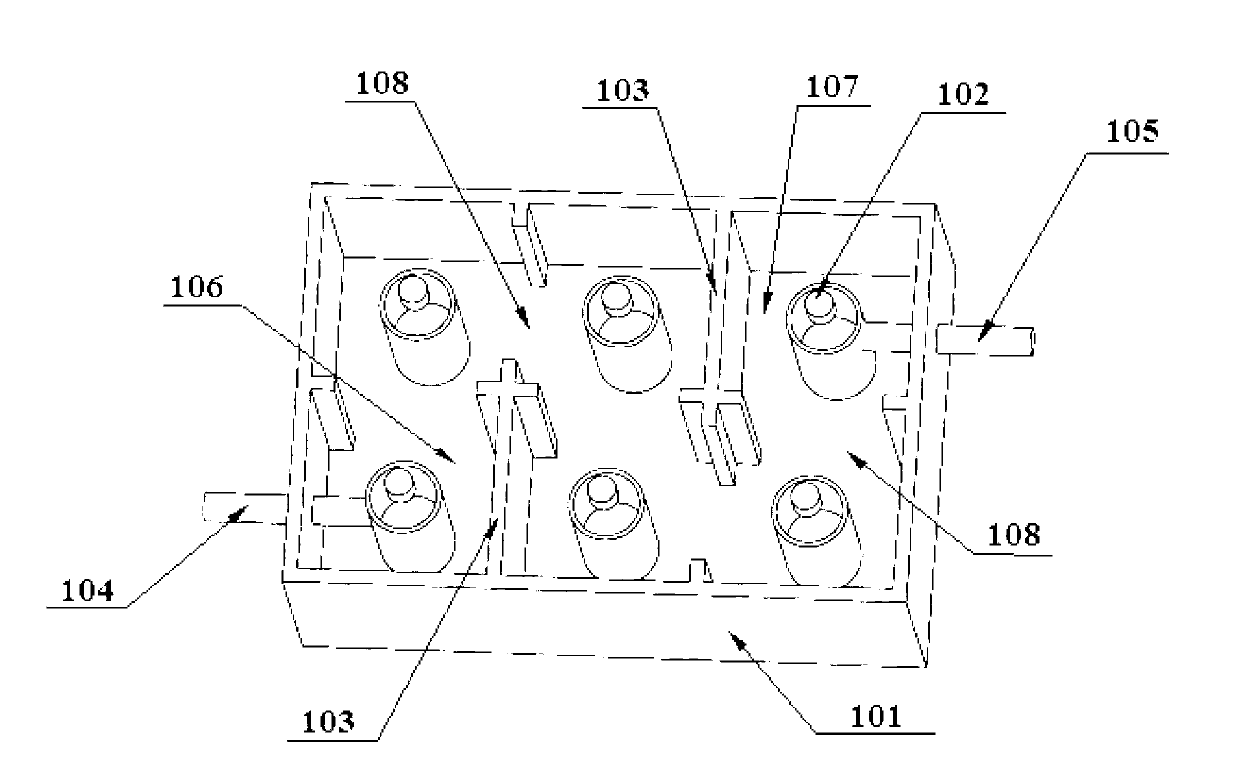
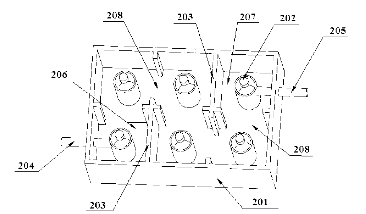
[0037] figure 2 A schematic structural diagram of the cavity filter in Embodiment 1 is shown. like figure 2 As shown, the cavity filter includes a shielding box 201 . The shielding box is a square box body. At least two resonant tubes 202 are arranged in the shielding box 201 . In the embodiment of the present invention, six resonant tubes 202 are arranged in the shielding box 201 . The number of resonance tubes 202 is set by those skilled in the art according to the design requirements or according to the technical indicators required by the system operator. The number of resonant tubes 202 in this embodiment is only exemplary, and does not limit the protection scope of the present invention.

[0038] The shielding box 201 is also provided with a partition wall 203 that isolates the inner space of the shielding box into resonant cavities with the same number as the resonant tubes. The specific arrangement is as follows: a partition wall 203 is provided between every a...

Embodiment 2

[0052] The structure of the cavity filter in the second embodiment is basically similar to that in the first embodiment, except that the depth of the tail cavity 207 is different from that of other resonant cavities. Image 6 A schematic structural diagram of the cavity filter in the second embodiment is shown. like Image 6 As shown, the depth of the first cavity 206 is the same as that of other resonant cavities. Wherein, the depth of the tail cavity 207 is smaller than the depth of the first cavity 206 and other resonant cavities, specifically, the depth difference ⊿h between the depth of the tail cavity 207 and the depth of the first cavity 206 and other resonant cavities ranges from 0 to the total depth of the resonant cavity Between 1 / 3, experiments have proved that if the difference ⊿h between the depth of the tail cavity 207 and the depth of other resonators is greater than 1 / 3 of the total depth of the resonator, the quality factor Q of the resonator will be seriousl...

Embodiment 3

[0057] The structure of the cavity filter in the third embodiment is basically similar to that in the first embodiment, except that the depths of the first cavity 206 and the tail cavity 207 are different from those of other resonant cavities: the first cavity 206 and the tail cavity 207 The depth of the first cavity 206 and the depth of the tail cavity 207 are the same in this embodiment. Figure 8 A schematic structural diagram of the cavity filter in Embodiment 3 is shown. like Figure 8 As shown, specifically, the difference ⊿h between the depth of the first cavity 206 and the tail cavity 207 and the depth of the first cavity 206 and other resonant cavities ranges from 0 to the total depth of the resonant cavity / 3.

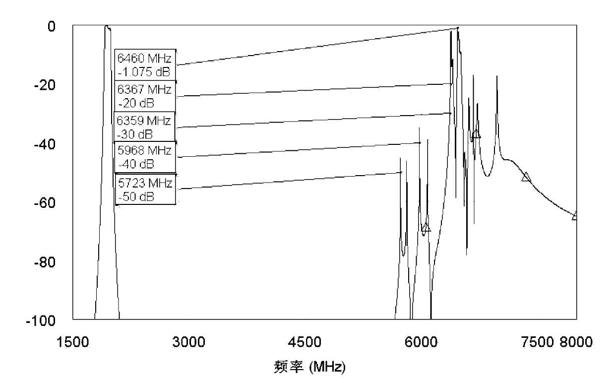
[0058] Figure 9 The transmission response curves of the cavity filter are shown when the depths of the first cavity 206 and the tail cavity 207 are both reduced by 5 mm from the bottom of the resonant cavity. like Figure 9 As shown, the passband frequenc...


PUM


Abstract

The invention discloses a cavity filter. The cavity filter comprises a shielding box. Isolating walls are arranged in the shielding box, the internal space of the shielding box is isolated into a plurality of sequentially communicated resonant cavities by the isolating walls, a resonating tube is arranged in each resonant cavity, and the depth of at least one resonant cavity in the shielding box is smaller than that of other resonant cavities. According to the cavity filter, the depth of at least one resonant cavity in the cavity filter is changed, a secondary mode frequency of a resonant frequency of the resonant cavities with changed depths is different from that of the secondary mode frequency of the resonant frequency of other resonant cavities in the cavity filter, thereby high frequency components of the secondary mode frequency generated by the resonant frequency of other resonant cavities are eliminated, the inhibiting effect on high-frequency noises mixed in microwave is achieved, and the far-end inhibition of the cavity filter can be improved. Simultaneously, the cavity filter has the advantages of being simple in structure, low in cost and beneficial to miniaturization development of the cavity filter.

Description

technical field [0001] The invention relates to the technical field of microwave communication, in particular to a cavity filter capable of improving remote suppression. Background technique [0002] Cavity filter is one of the main devices in microwave communication technology. It is widely used in electronic equipment such as communication, radar, navigation, electronic countermeasures, satellites, and test instruments. [0003] The prior art provides a cavity filter, see figure 1 , which includes a shielding box 101, six resonant tubes 102 are arranged in the shielding box 101, and the six resonant tubes 102 are arranged in two rows and three columns. Partition walls 103 are provided between each row of resonant tubes 102 and each column of resonant tubes 102 , and these partition walls 103 isolate the inner space of the shielding box 101 into six resonant cavities. Each resonant tube 102 is respectively arranged in a resonant cavity. Wherein, one end of each resonant ...

Claims


Application Information

Patent Timeline
Patent Type & Authority Applications(China)
IPC IPC(8): H01P1/208H01P7/06
Inventor 王伟东吴中林周力李龙章汪友兵
Owner TONGYU COMM INC
Why Eureka
Try Eureka