Dies and crimping method

A technology of assembly and molding, applied in the direction of connections, electrical components, conductive connections, etc.

Inactive Publication Date: 2013-03-27
YAZAKI CORP
View PDF5 Cites 16 Cited by
  • Summary
  • Abstract
  • Description
  • Claims
  • Application Information

AI Technical Summary

Problems solved by technology

[0013] The existing shielded wire terminal connection structure has encountered the following problems that need to be solved

Method used


Image

  • Dies and crimping method
  • Dies and crimping method
  • Dies and crimping method

Examples


Embodiment Construction

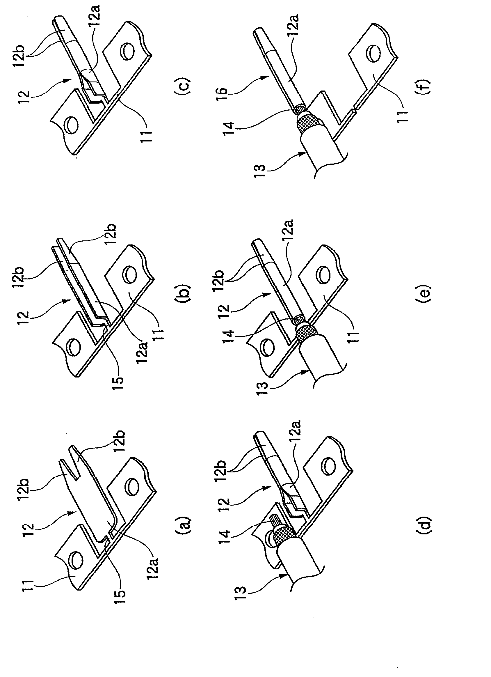
[0053] will be referred to below Figure 1 to Figure 5 (b) Describes the crimping method of the embodiment of the present invention.

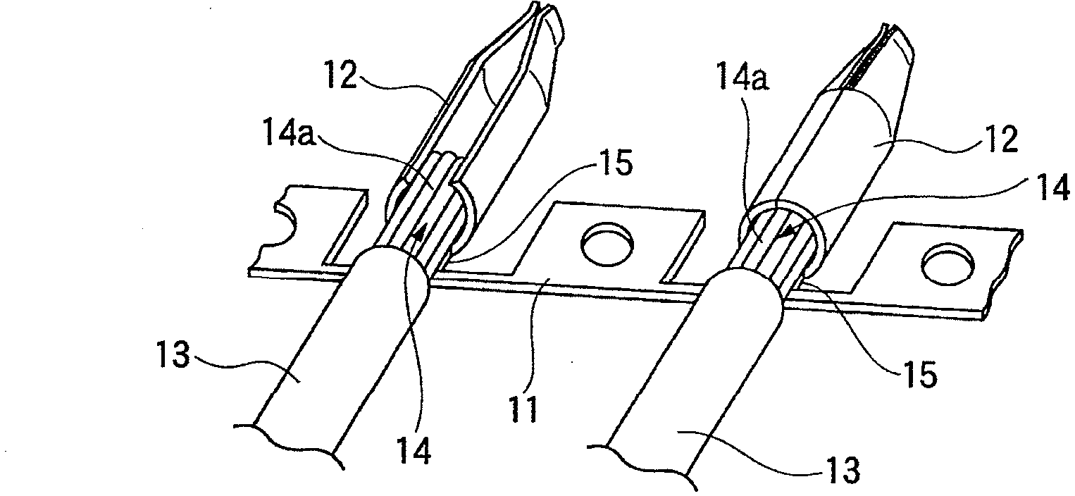
[0054] figure 1 The chain terminal of the embodiment shown in includes: a carrier 11 and a flat plate-shaped terminal forming piece 12 continuously provided at a plurality of positions of the carrier 11 along its longitudinal direction. The terminal forming sheet 12 is formed into a terminal by pressing. The ends of the signal conductors 14 of the electric wires 13 are accommodated in each terminal forming sheet 12 folded during the pressing work. The terminal forming pieces 12 are successively provided at a plurality of positions of the carrier 11 along the longitudinal direction thereof via respective carrier bridges 15 .

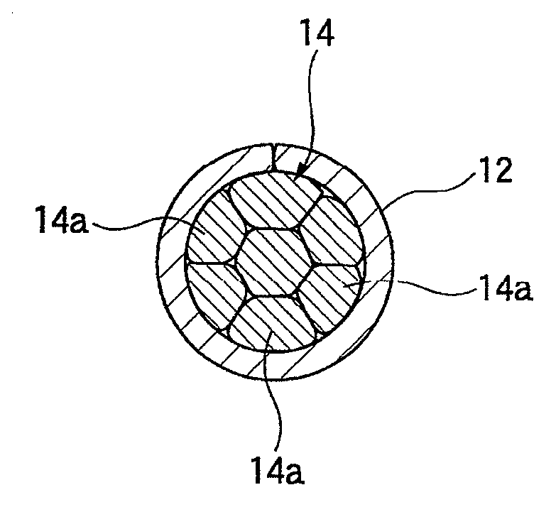
[0055] The signal conductor 14 is formed by bundling a plurality of core wires 14a. The ends of the signal conductors 14 are placed in the center of each terminal forming piece 12 . The right and left ends of the ter...


PUM


Abstract

The purpose of the present invention is to provide dies and a crimping method, wherein, when caulking a signal conductor of a wire placed on a terminal forming piece so as to wrap around the signal conductor, the signal conductor can be made not to bulge out from in-between both ends of the terminal forming piece. An upper die (18) of the present invention comprises a bulging-out preventing protrusion (17) that protrudes towards a signal conductor (14) arranged on the upper side of a terminal forming piece (12) placed on a lower die (19); and inner-die wall faces (18a) that are positioned at both sides of the bulging-out preventing protrusion (17), and that are for bending the terminal forming piece (12). When crimping the terminal forming piece (12) onto the signal conductor (14) with the upper die (18) and the lower die (19), the bulging-out preventing protrusion (17) presses the signal conductor (14) in the downward direction, and the inner-die wall faces (18a) bend the terminal forming piece (12) such that both end-sections of the terminal forming piece (12) will come near the bulging-out preventing protrusion (17).

Description

technical field [0001] The present invention relates to a die assembly for crimping a terminal to an electric wire having a signal conductor, such as a coaxial cable, and a crimping method using the die assembly. Background technique [0002] In the existing shielded electric wire terminal connection structure disclosed in Patent Document 1, the signal conductor connected to the inner conductor terminal is covered with the shielded conductor via an insulating inner cover, and the outer conductor terminal is connected to the end of the shielded electric wire in which the shielded conductor The outer periphery is covered by an insulating cover. [0003] The existing shielded wire terminal connection structure has a wire barrel consisting of a pair of crimping pieces for crimping the exposed shielded wire (conductor) at the end of the shielded wire to an external conductor terminal by crimping. The process of crimping the shielded wire through the crimping piece of the wire ba...

Claims


Application Information

Patent Timeline
Patent Type & Authority Applications(China)
IPC IPC(8): H01R43/048B21D39/00H01R4/18
CPCB21D39/048H01R4/184H01R43/0482H01R43/048H01R43/28H01R43/055Y10T29/53235H01R43/058
Inventor 森川大史
Owner YAZAKI CORP
Why Eureka
Try Eureka