Mixing head device

A technology of mixing head and mixing body, which is applied to the device and coating of the surface coating liquid, can solve the problems such as the reduction of the production efficiency of the continuous production line of the sandwich panel.

Active Publication Date: 2013-04-03
HENAN TIANFON ENERGY SAVING PANEL SCI & TECH
View PDF7 Cites 6 Cited by
  • Summary
  • Abstract
  • Description
  • Claims
  • Application Information

AI Technical Summary

Problems solved by technology

[0003] The purpose of the present invention is to provide a mixing head device, which aims to solve the problem that the mixing head device in the prior art needs to b...

Method used


Image

  • Mixing head device
  • Mixing head device
  • Mixing head device

Examples


Embodiment Construction

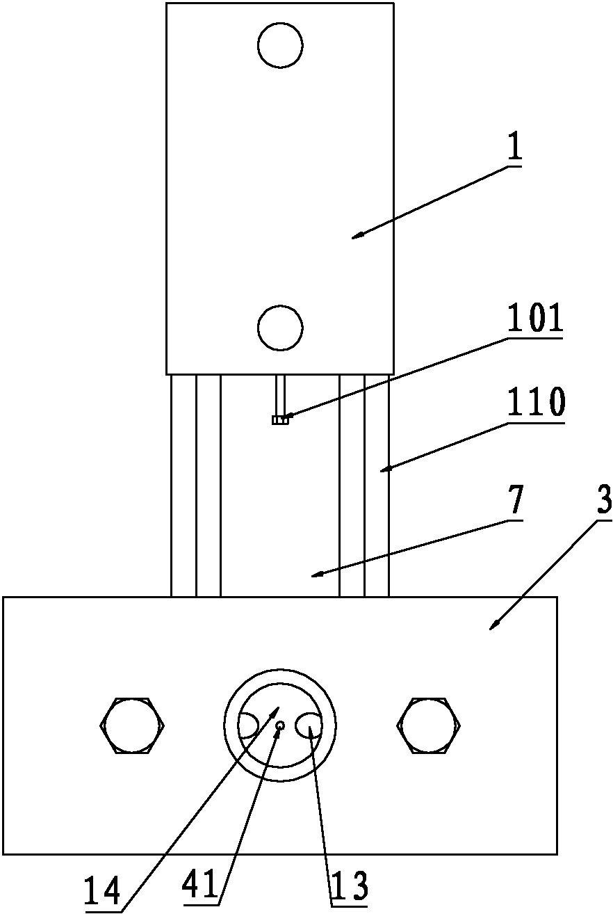
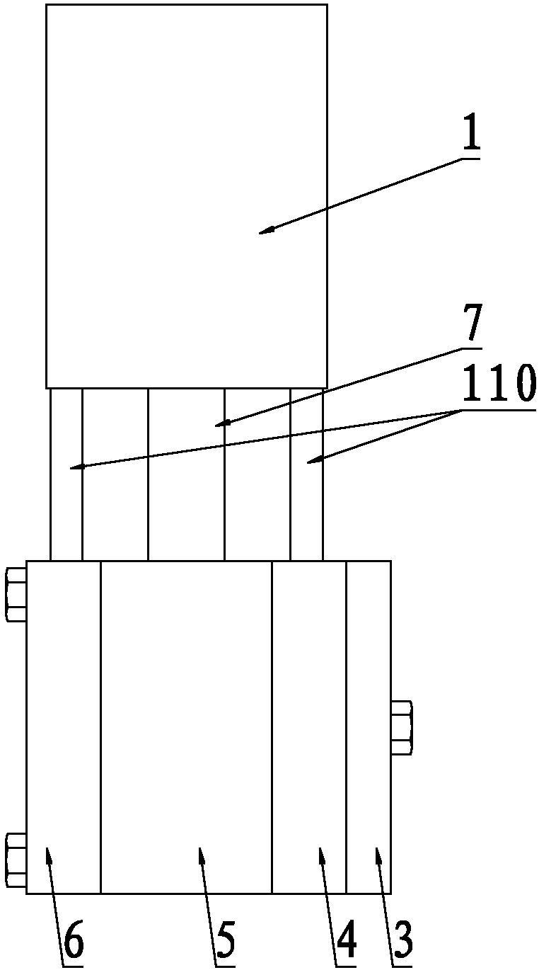
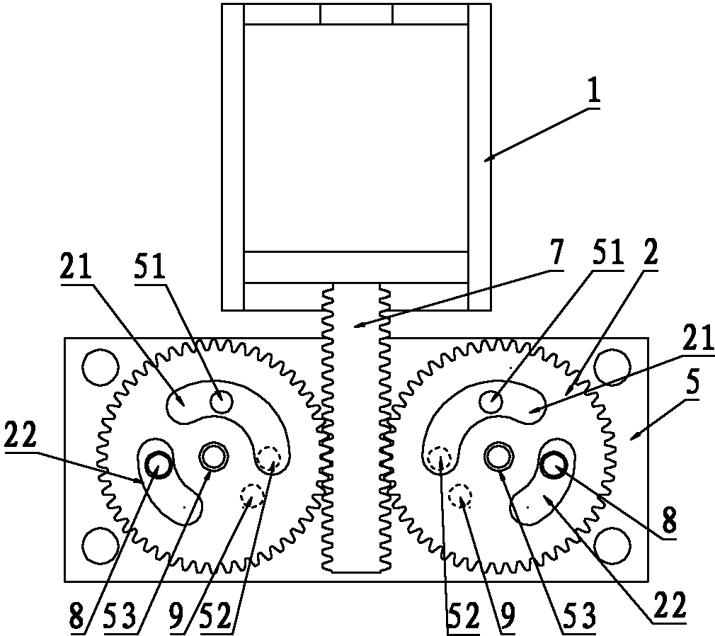
[0029] Embodiments of the mixing head device of the present invention: as Figure 1 to Figure 13 As shown, the mixing head device is located between the feed pipe and the discharge pipe, and the mixing head device is mainly composed of three parts: the main body of the device, the driving cylinder 1 and the regulating wheel 2. The main body of the device includes a mixing plate 3, a partition 4, a hollow cubic main valve body 5, and a pressure plate 6 fixedly connected in sequence from front to back, wherein the shape of the cavity of the main valve body 5 is a cube, and the front and rear side walls of the cavity are Symmetrically spaced planes. Adjusting wheel 2 is two gears, and is assembled in the left and right sides of cavity by the rotation of positioning sleeve 53, and the end face of adjusting wheel 2 is all parallel with the front and rear side walls of cavity. The driving cylinder 1 is fixed on the top of the main valve body 5 through the connecting stud 110, and t...


PUM


Abstract

The invention discloses a mixing head device. According to the mixing head device, a two-position four-way valve is additionally arranged in each material branch path in a feeding part; due to the two-position four-way valves, when the mixing head is in a working state, feeding ports and discharge ports are communicated, and return material ports and washing ports are closed; when the mixing head is in a washing state, the feeding ports and the return material ports are communicated, the discharge ports are communicated with the washing ports, and discharge ports of the two-position four-way valves are communicated with the inlets of a mixing main body through pipelines, and the inlets of the mixing main body are communicated with the outlets of the mixing main body after being gathered together so as to be in the washing state, the material returns to a material storage device through the two-position four-way valves, the mixing device and the pipelines are washed through the two-position four-way valves by using a cleaning agent, and therefore the mixing head provided by the invention is washed in an on line manner; and the purpose of accomplishing the washing task without halting the machine and the production is achieved.

Description

technical field [0001] The invention relates to the technical field of material mixing machinery, in particular to a mixing head device. Background technique [0002] The existing sandwich panel continuous production line is divided into upper and lower color steel plate forming production lines, sandwich panel production lines and glue-sprayed fabric production lines according to the process. The overall production process includes: surface material uncoiling, cutting, roll forming, sandwich panel cutting, conveying , surface material upper and lower preheating, upper and lower glue spraying, double-pressure curing molding, follow-up fixed-length cutting, packaging and palletizing, etc. The main production process of the upper and lower glue spraying production line includes: automatic feeding→storage tank→mixing →Temperature adjustment system→Conveying material pump→Pipeline→Servo motion material distributing mechanism→Mixing head device, all realize automatic continuous p...

Claims


Application Information

Patent Timeline
IPC IPC(8): B05C5/02B05C11/00B05C11/10
Inventor 王玉彬王晓瀛刘卫兵
Owner HENAN TIANFON ENERGY SAVING PANEL SCI & TECH
Why Eureka
Try Eureka