Straight pipe end clamping device of pipe expanding machine

A technology of a clamping device and a tube expander, which is applied in the field of clamping devices, can solve the problems of poor clamping consistency, difficult control, and unstable clamping, and achieves compact structure, improved consistency, and uniform force distribution. reasonable effect

Active Publication Date: 2013-04-03
JDM JINGDA MASCH (NINGBO) CO LTD
View PDF9 Cites 11 Cited by
  • Summary
  • Abstract
  • Description
  • Claims
  • Application Information

AI Technical Summary

Problems solved by technology

However, the clamping device of the straight pipe end of the existing tube expand

Method used


Image

  • Straight pipe end clamping device of pipe expanding machine
  • Straight pipe end clamping device of pipe expanding machine
  • Straight pipe end clamping device of pipe expanding machine

Examples


Embodiment Construction

[0020] The present invention will be further described in detail below in conjunction with the accompanying drawings and embodiments.

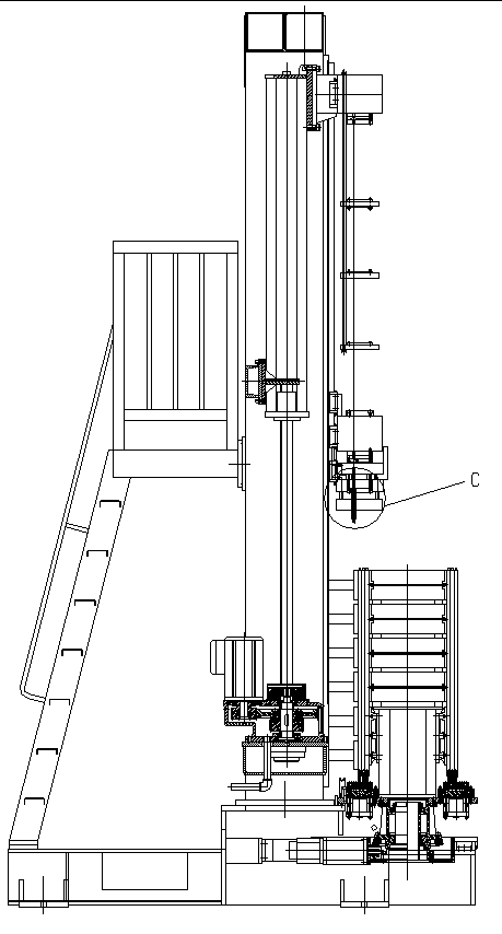
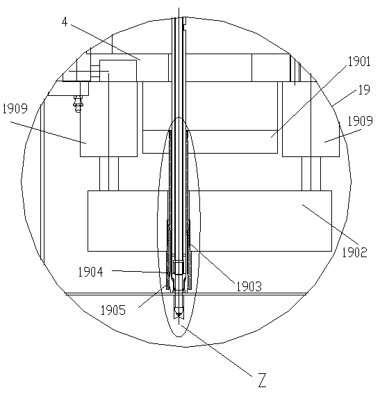
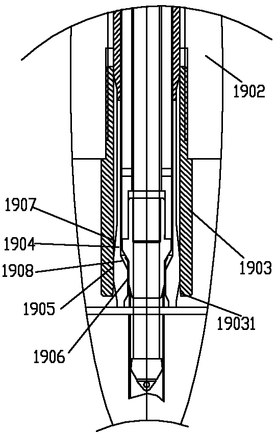
[0021] Such as figure 1 , 2 As shown, the straight pipe end clamping device 19 of the tube expander includes a clamping jaw mounting plate 1901 and a clamping sleeve mounting plate 1902 installed on the ejector base 4, and a clamping jaw 1904 is mounted on the clamping jaw mounting plate 1901. The tight sleeve 1903 is installed on the clamping sleeve mounting plate 1902, the head of the clamping jaw 1904 is provided with a cylindrical surface 1905 behind the largest conical surface, and there are several slits along the axial direction, and the clamping sleeve 1903 passes through The clamping sleeve mounting plate 1902 moves up and down to realize the opening and closing of the jaw 1904 head, thereby realizing the clamping and loosening of the straight pipe end of the workpiece. The driving mechanism oil cylinder 1909 drives the clamping slee...


PUM


Abstract

The invention relates to a straight pipe end clamping device of a pipe expanding machine. The clamping device comprises a clamping jaw mounting plate and a clamping sleeve mounting plate, wherein the clamping jaw mounting plate and the clamping sleeve mounting plate are arranged on a stripping seat, clamping jaws are arranged on the clamping jaw mounting plate, the back part of the largest conical surface of the head of each clamping jaw is provided with a section of cylindrical surface, the head of each clamping jaw is provided with a plurality of slots in the axial direction, a clamping sleeve is sheathed outside the clamping jaws and is arranged on the clamping sleeve mounting plate, the clamping sleeve mounting plate is driven by a driving mechanism to do vertical reciprocating movement, and then the clamping sleeve looses and closes the slots of the heads of the clamping jaws. When the heads of the clamping jaws are clamped, the inner cylindrical surface of the clamping sleeve is clamped with the sections of cylindrical surfaces of the heads of the clamping jaws, so the clamping is more reliable, the clamping process is more stable and is easier to control, and the clamping amount is controllable; and meanwhile, the position requirement is reduced when the clamping sleeve and the clamping jaws are clamped, the precision requirement on the driving mechanism of the clamping sleeve is also reduced, particularly under the condition of more clamping jaws, the original phenomenon of asynchronous clamping caused by nonuniform clamping points of each clamping jaw is avoided, and the uniformity of the clamping jaws during clamping is improved.

Description

technical field [0001] The invention relates to a clamping device of a tube expander. Background technique [0002] The tube expander expands the diameter of many heat exchanger tubes placed in the heat sink, so that they are closely combined with the heat sink to avoid loosening and increase the thermal conductivity of the heat exchanger. In addition, the ends of the tubes are flared and turned side, in order to facilitate the next process. [0003] When the tube expander is expanding the tube, the tube parts to be expanded will shrink and so on, so many tube parts need to be fixed well. However, the clamping device of the straight pipe end of the existing tube expander is unstable and difficult to control, and the clamping consistency is not good. Contents of the invention [0004] The technical problem to be solved by the present invention is to overcome the above-mentioned defects of the prior art and provide a straight pipe end clamping device of a tube expander, so...

Claims


Application Information

Patent Timeline
IPC IPC(8): B21D39/08B21D41/02B21D19/00
Inventor 郑良才谢文杰
Owner JDM JINGDA MASCH (NINGBO) CO LTD
Why Eureka
Try Eureka