Follow-up clamping device

A technology of clamping device and clamping mechanism, which is applied in the direction of positioning device, clamping, supporting, etc., can solve the problems of deviation of the center of gravity of pipe fittings, clamping pipe fittings, and looseness of the clamping head, etc., and achieves simple and reliable adjustment, reasonable structure, and guarantee The effect of process precision

Active Publication Date: 2013-04-03
SUZHOU JWELL MACHINERY
View PDF5 Cites 16 Cited by
  • Summary
  • Abstract
  • Description
  • Claims
  • Application Information

AI Technical Summary

Problems solved by technology

[0002] As attached Figure 1 and attached Figure 2 It is shown that the clamping device used for clamping and positioning the pipe fittings in the traditional technology first supports the pipe fittings through the supporting parts below, and then controls the corresponding four resisting parts at an angle of 90 degrees through four cylinders. The clamping head clamps the pipe fitting, so that the weight of the entire pipe fitting is completely borne by the two lower clamping heads. Generally, the quality of the pipe fitting is relatively large. When cutting the pipe fitting, etc., the center of gravity of the pipe fitting will often deviate. , and it is difficult to re-adjust the center, it will cause the clamping head in the corresponding direction to loosen and can no longer clamp the pipe stably, making it difficult to meet the accuracy requirements in subsequent operations

Method used


Image

  • Follow-up clamping device
  • Follow-up clamping device
  • Follow-up clamping device

Examples


Embodiment Construction

[0022] Below in conjunction with the embodiment shown in the accompanying drawings, the present invention is described in detail as follows:

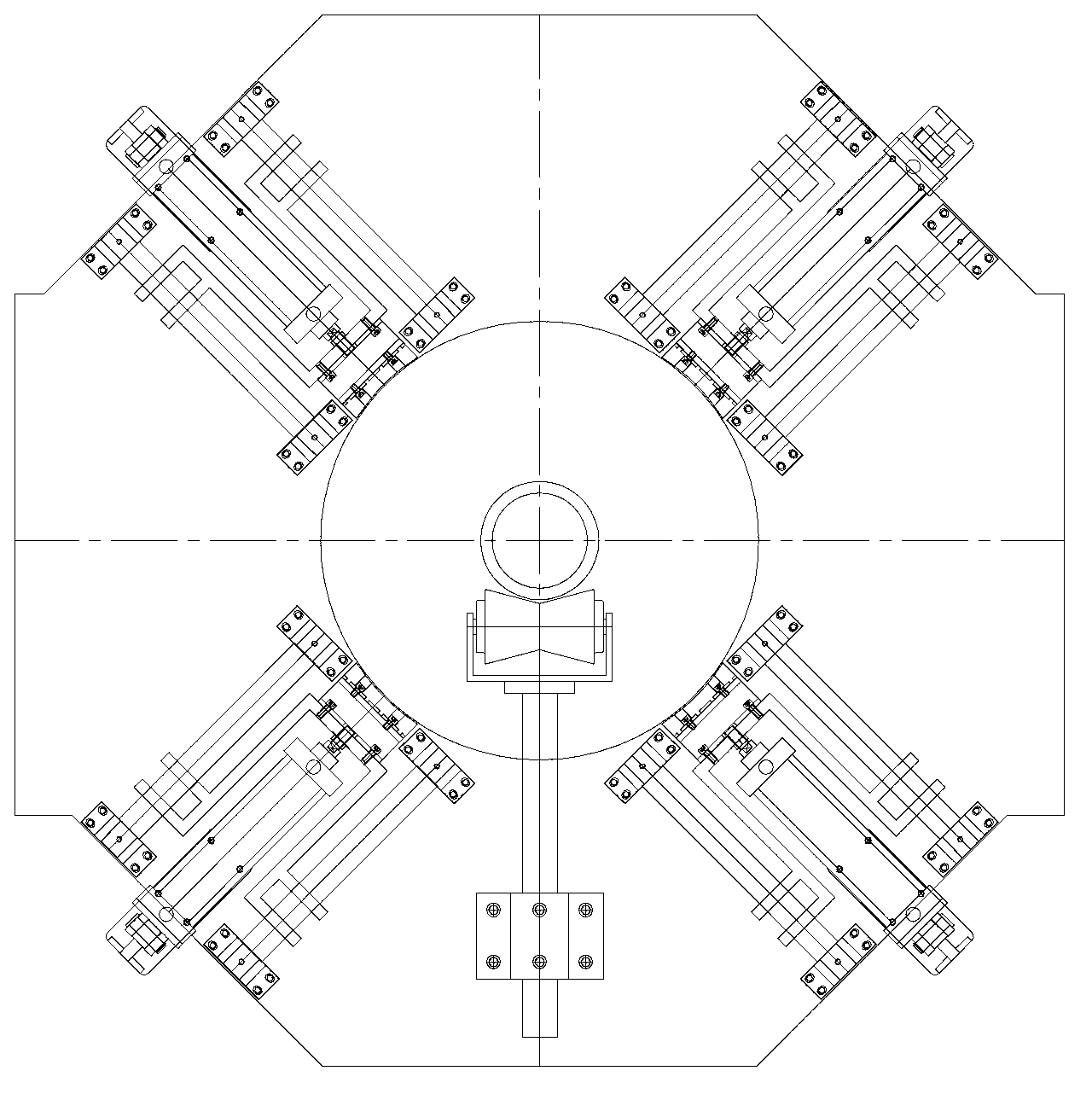
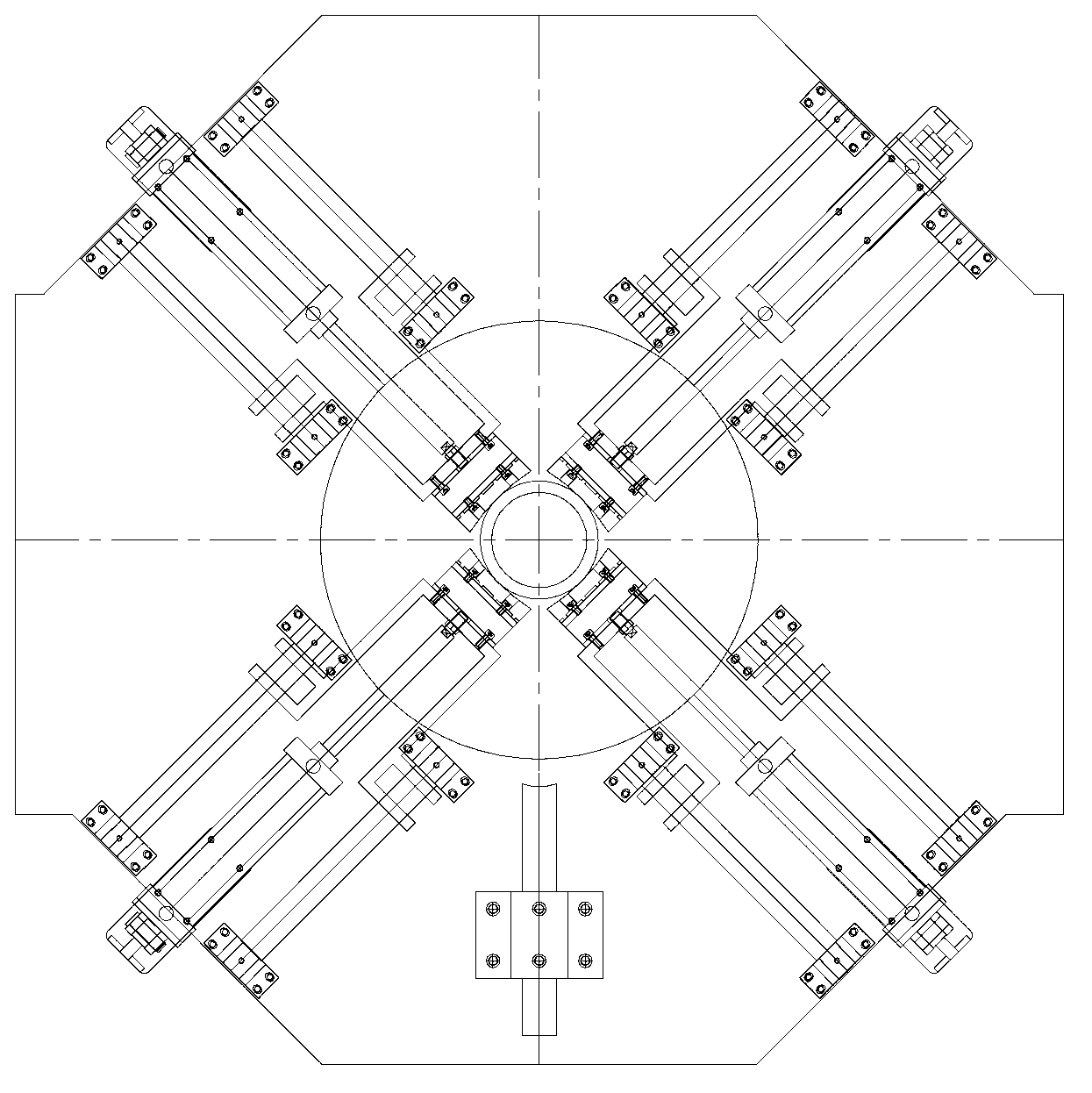
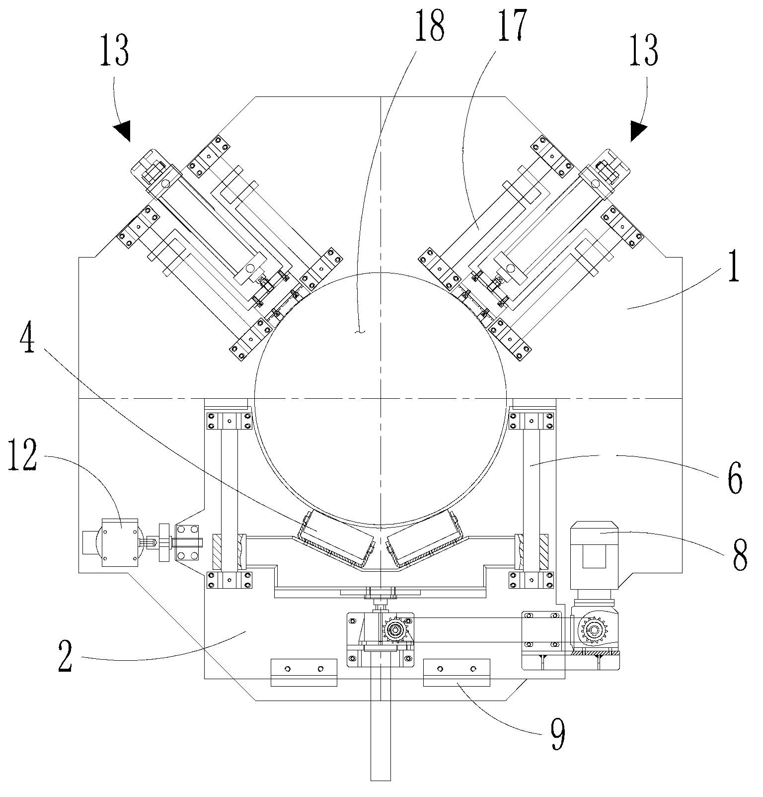
[0023] The "left and right" direction in this manual refers to the attached image 3 and attached Figure 4 The left and right direction, "vertical" direction in the image 3 and attached Figure 4 The up and down direction and "horizontal" direction in the image 3 and attached Figure 4 in the left-right direction.

[0024] as attached image 3 , attached Figure 4 and attached Figure 5 As shown, the follow-up clamping device of the present invention is used to clamp and fix the pipe fitting 19 so as to perform other operations on the pipe fitting 19. The device includes a first supporting body 1, which is slidably arranged on the first supporting body 1 The second supporting body 2, the clamping mechanism fixedly arranged on the first supporting body 1 and the supporting mechanism which can be lifted and lowered...


PUM


Abstract

The invention discloses a follow-up clamping device for clamping and positioning pipe pieces. The device comprises a first bearing body, a second bearing body arranged on the first bearing body in a sliding manner, a clamping mechanism fixed on the first bearing body, and a bearing mechanism arranged on the second bearing body in a lifting manner, wherein the clamping mechanism comprises two groups of telescopic butting heads forming angles; the two groups of butting heads are symmetrically arranged left and right; the bearing mechanism comprises two rows of rollers symmetrically arranged left and right; rotating axle lines of the rollers in one group are parallel to one another, and are positioned in a same plane; two planes, where the rotating axle lines of the two rows of rollers are positioned, are intersected with each other; the pipe pieces are clamped between the two groups of butting heads and the two rows of rollers; and each of the rollers is arranged along the tangential direction of the pipe pieces. The pipe pieces are stably clamped and positioned through the two rows of rollers and the two groups of butting heads so as to provide guarantee to the technique precision of following operations for the pipe pieces; and the device has a reasonable structure, is easily and reliably adjusted, and is suitable for the pipe pieces with different pipe diameters.

Description

technical field [0001] The invention relates to a device for clamping and positioning pipe fittings, in particular to a follow-up clamping device. Background technique [0002] as attached figure 1 and attached figure 2 As shown, the clamping device used for clamping and positioning the pipe fittings in the traditional technology first supports the pipe fittings through the lower supporting parts, and then controls the corresponding four cylinders at an angle of 90 degrees to each other through four cylinders. The clamping head clamps the pipe fittings, so that the weight of the entire pipe fitting is completely borne by the two pressing heads below. Generally, the quality of the pipe fittings is relatively large. When the pipe fittings are cut and other operations are performed, the center of gravity of the pipe fittings will often occur. Deviation, and it is difficult to re-adjust the center, it will lead to the loosening of the clamping head in the corresponding direc...

Claims


Application Information

Patent Timeline
Patent Type & Authority Applications(China)
IPC IPC(8): B23Q3/00
Inventor 何海潮王淳德
Owner SUZHOU JWELL MACHINERY
Why Eureka
Try Eureka