Manufacturing method of functional vacuum glass

A vacuum glass and manufacturing method technology, applied in glass manufacturing equipment, glass molding, glass reshaping, etc., can solve the problems of undiscovered patent documents, impact on sound insulation, heat insulation, limited production area, etc., and achieve scientific design , high sound insulation and heat insulation effect, and the effect of expanding the technical field

Inactive Publication Date: 2013-04-03
天津盛泰通达机电技术咨询有限公司
View PDF13 Cites 0 Cited by
  • Summary
  • Abstract
  • Description
  • Claims
  • Application Information

AI Technical Summary

Problems solved by technology

[0002] Insulating glass is composed of a hollow cavity formed between two flat glasses, which has certain sound insulation, heat insulation and sealing effects, simple process, low cost, and widely used; vacuum glass is a vacuum cavity formed between two flat glasses, sound insulation , Heat insulation and sealing effects are greatly improved compared with insulating glass, but the process is complicated and the cost is high
In addition, there is no support body in the hollow cavity of insulating glass, so the production area is relatively limited; while support bodies are uniformly arranged in the vacuum cavity of vacuum glass. Cavity volume less than 20cm 3 , affecting the effect of sound insulation and heat insulation
[0004] Through searching, no published patent documents related to the application of the present invention have been found

Method used


Image

  • Manufacturing method of functional vacuum glass
  • Manufacturing method of functional vacuum glass
  • Manufacturing method of functional vacuum glass

Examples


Embodiment 1

[0026] A method for manufacturing functional vacuum glass, the steps are:

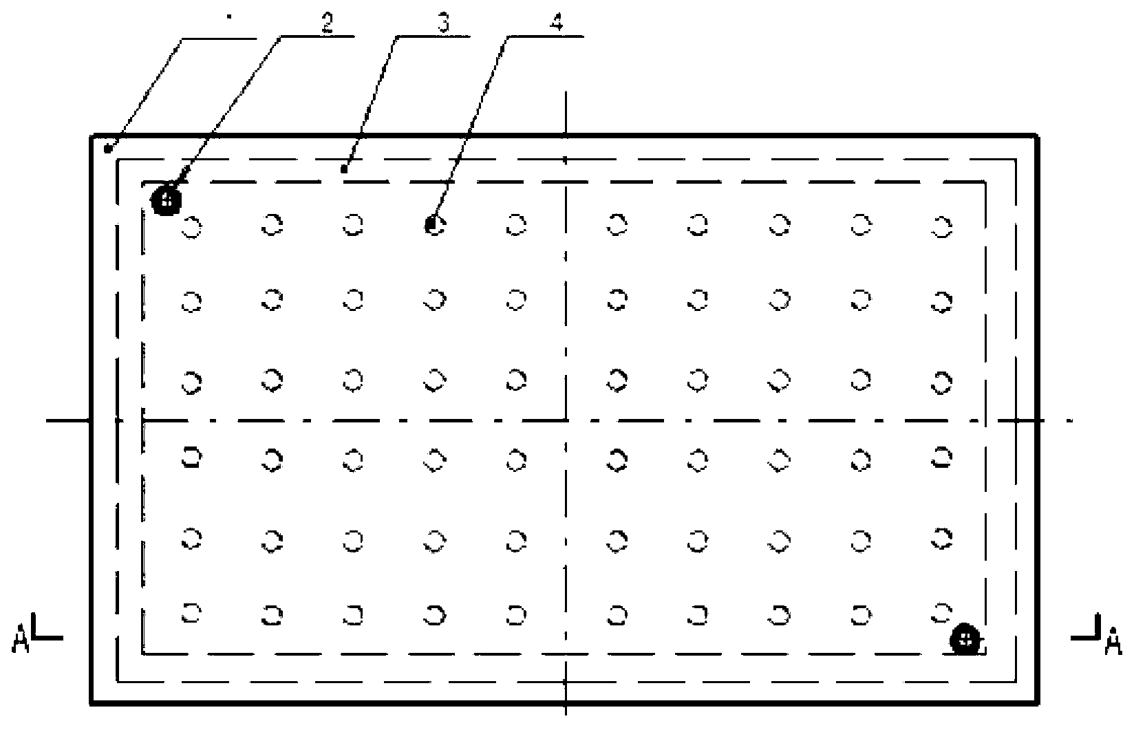
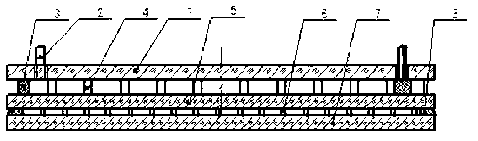
[0027] (1) Place the finished vacuum glass on the operating table. The vacuum glass includes the top glass 5 and the base glass 7, and supports 6 are evenly spaced between them, and the edge between the top glass and the base glass is sealed with Edge sealing with low melting point glass powder8. Place the flat glass on the vacuum glass (the top glass and the substrate glass are both acceptable, the attached glass in this embodiment is the top glass) on the operating table, and place the support body 4 on the upper surface at an even interval of 3-5 cm. The support body includes glass, ceramics, metal support column, metal wire or metal sheet, and the height of the support body is 0.5-25mm; for the cylindrical support body, its diameter is Ф1-15mm;

[0028] (2) Place the square frame 3 coated with low-melting point glass powder on the upper and lower ends on the four sides of the upper glass of the va...

Embodiment 2

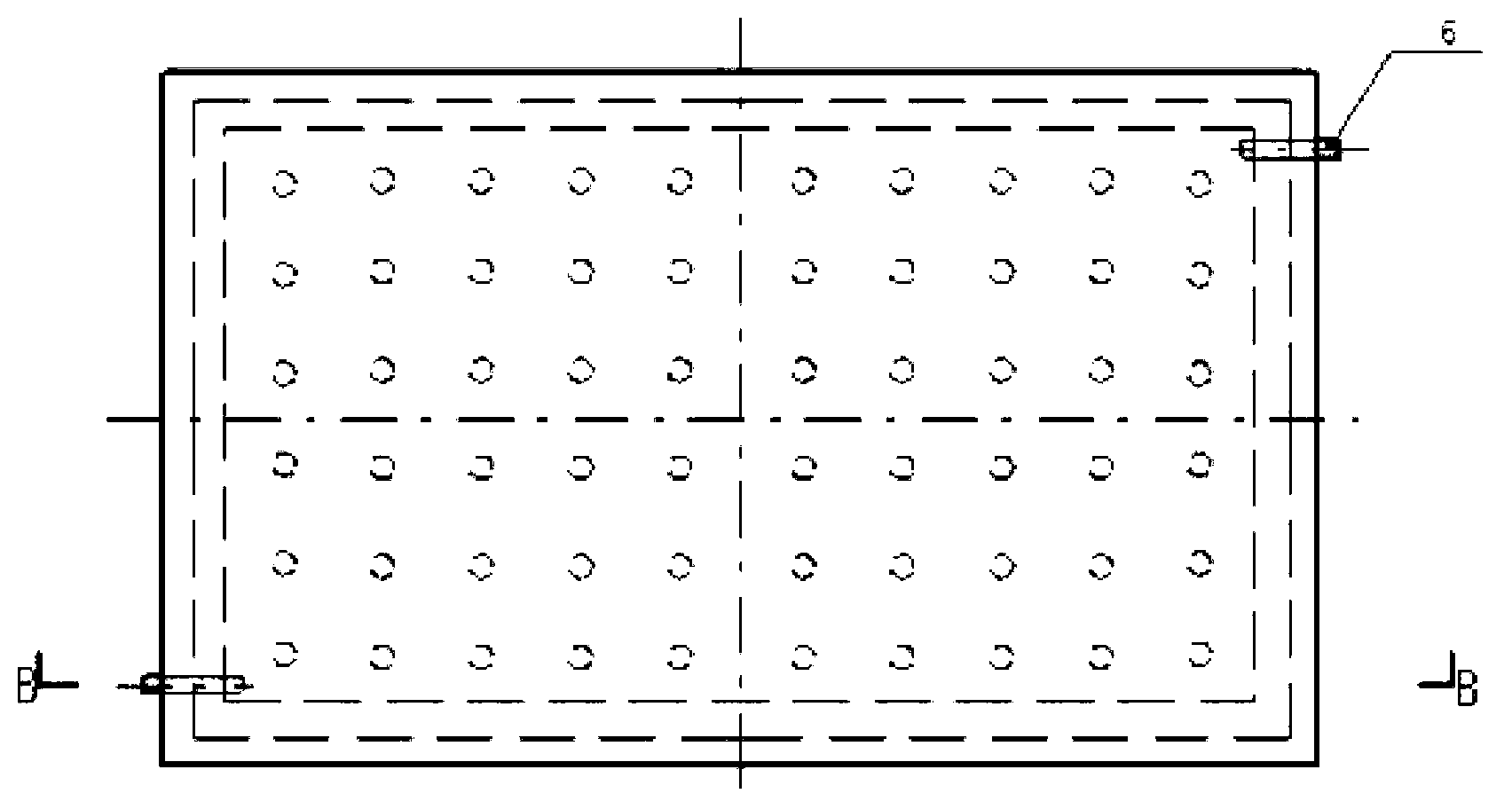
[0038] Only the glass tube 9 is fixed on the square frame, that is, the exhaust glass tube is placed on the side or corner of the square frame, and a concave hole can be made on the square frame and between the corresponding flat glass and the upper glass in advance. The tank is then filled with placed glass tubes and low-melting glass powder.

[0039] In the accompanying drawings of this embodiment, the two glass tubes are also installed diagonally.

[0040] The unrecited part is the same as the embodiment.


PUM

PropertyMeasurementUnit
heightaaaaaaaaaa
heightaaaaaaaaaa

Abstract

The invention relates to a manufacturing method of functional vacuum glass, which comprises the following steps: (1) placing vacuum glass on an operating console, and uniformly placing supports on the upper surface of the vacuum glass at intervals; (2) placing a frame at four sides of the vacuum glass, wherein the upper end surface and the lower end surface of the frame is uniformly coated with low-melting glass powder; (3) forming at least one through hole communicated with a cavity in the frame, placing a glass tube on the through hole, and filling glass powder at the periphery of the glass tube; (4) laminating plate glass and the vacuum glass; and (5) placing into a heating furnace, heating to 300-500 DEG C to melt the low-melting glass, cooling, and then sealing to form the functional vacuum glass provided with the glass tube and the hollow sealing cavity. According to the invention, the vacuum glass is organically combined with the functional glass to form combined glass, thereby achieving high sound insulation and heat insulation effects of the vacuum glass and properties of the hollow glass and functional glass, and widening the technical field of glass.

Description

technical field [0001] The invention belongs to the field of vacuum glass, in particular to a method for manufacturing functional vacuum glass. Background technique [0002] Insulating glass is composed of a hollow cavity formed between two pieces of flat glass, which has certain effects of sound insulation, heat insulation and sealing. The process is simple, the cost is low, and it is widely used; , Heat insulation and sealing effects are greatly improved compared with insulating glass, but the process is complicated and the cost is high. In addition, there is no support body in the hollow cavity of insulating glass, so the production area is relatively limited; while support bodies are uniformly arranged in the vacuum cavity of vacuum glass. Cavity volume less than 20cm 3 , affecting the effect of sound insulation and heat insulation. [0003] With the development of science and technology, the application prospects of vacuum glass and insulating glass are getting wider...

Claims


Application Information

Patent Timeline
Patent Type & Authority Applications(China)
IPC IPC(8): C03B23/24
Inventor 苏再林
Owner 天津盛泰通达机电技术咨询有限公司
Why Eureka
Try Eureka