Reclamation-area factory building column foundation and construction protection method thereof

A plant column and foundation technology, applied in basic structure engineering, protection devices, buildings, etc., can solve the problems of long construction period, complex wall construction process, poor economic benefits, etc., to save steel consumption, improve stiffness characteristics, The effect of increasing economic efficiency

Active Publication Date: 2013-04-03
鞍钢集团工程技术有限公司
View PDF5 Cites 0 Cited by
  • Summary
  • Abstract
  • Description
  • Claims
  • Application Information

AI Technical Summary

Problems solved by technology

[0002] At present, the construction protection technologies for factory building column foundations in reclamation areas in industrial buildings mainly include reinforced concrete walls, plastic concrete walls, solidified mortar walls, self-hardening mud walls, prefabricated walls, and mud groove walls (backfilling gravel, clay and cement composite), There are several kinds of post-tensioned prestressed underground diaphragm walls and steel diaphragm walls, but the construction process of the above walls is complex, the construction period is long, and the economic benefits are not good

Method used


Image

  • Reclamation-area factory building column foundation and construction protection method thereof
  • Reclamation-area factory building column foundation and construction protection method thereof
  • Reclamation-area factory building column foundation and construction protection method thereof

Examples


Embodiment Construction

[0016] The specific embodiment of the present invention will be further described below in conjunction with accompanying drawing:

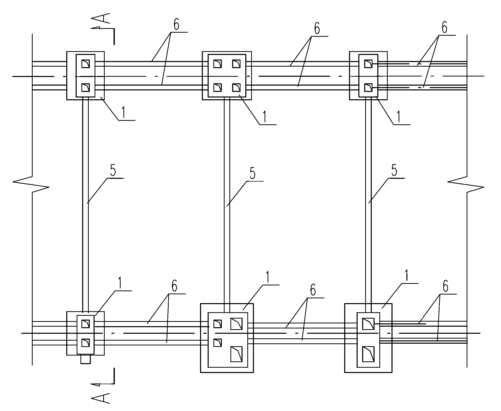
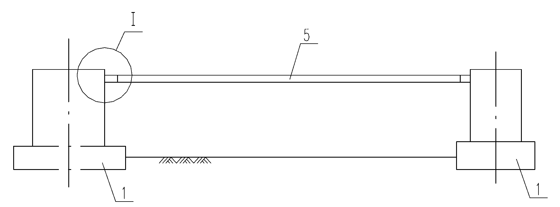
[0017] Such as figure 1 , is a schematic diagram of the plane structure of the column foundation construction of the factory building of the present invention. The column foundation body 1 is located in the reclamation area, and its vertical adjacent column foundation bodies 1 are connected by concrete longitudinal connecting beams 6, and the horizontal span adjacent column foundation bodies are passed through a process. The top pipe 5 is connected. Determine the span, section, and reinforcement of the concrete longitudinal connecting beam 6 according to the column spacing and load of the factory building, and complete the pouring of the concrete longitudinal connecting beam 6; then determine the length of the process pipe jacking 5 according to the span and geological conditions of the factory building. Load calculation process The diameter and ...


PUM


Abstract

The invention relates to the field of industrial buildings, in particular to a reclamation-area factory building column foundation and a construction protection method thereof. The reclamation-area factory building column foundation comprises stand column foundation bodies and is characterized in that longitudinal adjacent stand column foundation bodies are connected with each other through a longitudinal concrete connecting beam, and the transverse-span adjacent stand column foundation bodies are connected with each other through a process push pipe; the process push pipe comprises supports, short pipes, lining pipes and pull pipes, and the supports are respectively arranged on bearing platforms of the adjacent stand column foundation bodies; one section of short pipe is arranged on each support, and a pull pipe is arranged between the short pipes of the adjacent factory building column foundations; the lining pipes are arranged in the connecting positions of the pull pipes and the short pipes, and the outer diameters of the lining pipes are in clearance fit with the inner diameters of the pull pipes and the short pipes; and pins are arranged on the outer diameters of the lining pipes, and one end of each pin extends out from a long hole at the end part of each short pipe. Compared with the prior art, the reclamation-area factory building column foundation has the benefits that the longitudinal deformation is limited by utilizing the longitudinal connecting beam, the problem that the deformation caused by the transverse load of the factory building column foundation is overlarge is solved by adopting the reusable process push pipes, and the steel consumption is saved.

Description

technical field [0001] The invention relates to the field of industrial buildings, in particular to a factory building column foundation in a reclamation area and a construction protection method thereof. Background technique [0002] At present, the construction protection technologies for factory building column foundations in reclamation areas in industrial buildings mainly include reinforced concrete walls, plastic concrete walls, solidified mortar walls, self-hardening mud walls, prefabricated walls, and mud groove walls (backfilling gravel, clay and cement composite), There are several kinds of post-tensioned prestressed underground diaphragm walls and steel diaphragm walls, but the construction process of the above walls is complicated, the construction period is long, and the economic benefits are not good. Contents of the invention [0003] The purpose of the present invention is to provide a factory building column foundation and its construction protection metho...

Claims


Application Information

Patent Timeline
IPC IPC(8): E02D27/42E02D27/34E02D31/00
Inventor 尹子峰鲁大勇尚岩松张金浩李文张金岭周苏
Owner 鞍钢集团工程技术有限公司
Why Eureka
Try Eureka