Orthogonal polarization fiber bragg grating vector torsion sensing device and detection method thereof

An orthogonal polarization and fiber grating technology, applied in the direction of measuring devices, optical devices, instruments, etc., can solve the problems of not being able to obtain polarization state energy information at the same time, not being able to realize vector torsion detection, and large volume of the sensing system, so as to avoid Splice loss and unpredictable polarization interference, guaranteed mechanical strength and polarization stability, and adjustable scanning bandwidth

Active Publication Date: 2013-04-03
JINAN UNIVERSITY
View PDF5 Cites 16 Cited by
  • Summary
  • Abstract
  • Description
  • Claims
  • Application Information

AI Technical Summary

Benefits of technology

This patented technical effect of this inventor's innovative twin-focal type sensory device lies within three main features - accuracy, efficiency, flexibility, and security against environmental factors like heat or vibrations. It includes an improved version called CFOG gratings, which allows for precise measurements without distortion due to thermal variations. Additionally, there is also incorporated into the device a special process called coherer compensator, where each component helps stabilizing the rotational axis while reducing errors induced through external influences. Overall, these improvements improve performance and reliability of the overall device.

Problems solved by technology

Technological Problem: Current Torque Tensor designs have limitations such as bulky weight or complicated manufacturing processes due to complex fabrication techniques used during production. Additionally, current methods require expensive equipment like electric magnetic induction machines, electrostrictive force devices, and magnetoeletron gratings, making them difficult to integrate onto smaller electronic components without compromising their performance capabilities.

Method used


Image

  • Orthogonal polarization fiber bragg grating vector torsion sensing device and detection method thereof
  • Orthogonal polarization fiber bragg grating vector torsion sensing device and detection method thereof
  • Orthogonal polarization fiber bragg grating vector torsion sensing device and detection method thereof

Examples


Embodiment 1

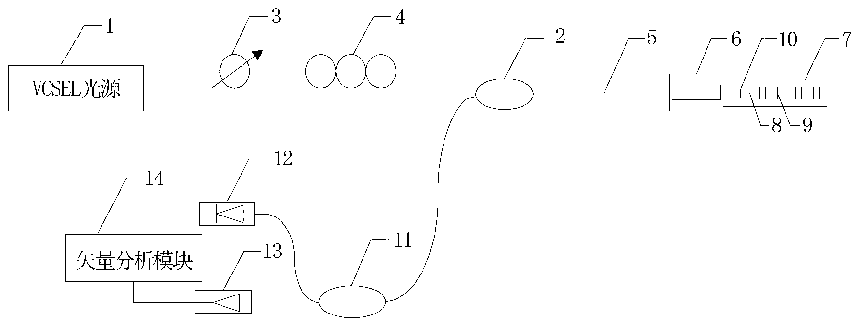
[0045] Such as figure 1 and figure 2 As shown, the twist sensing device of this embodiment includes a VCSEL light source 1, a polarization processing unit, a sensing probe, an orthogonal polarization demodulation processing unit, and a fiber coupler 2. The polarization processing unit, the sensing probe, and an orthogonal polarization The demodulation processing unit is connected through an optical fiber coupler 2;

[0046] The polarization processing unit includes a polarizer 3 and a polarization controller 4, and the VCSEL light source 1, the polarizer 3 and the polarization controller 4 are sequentially connected;

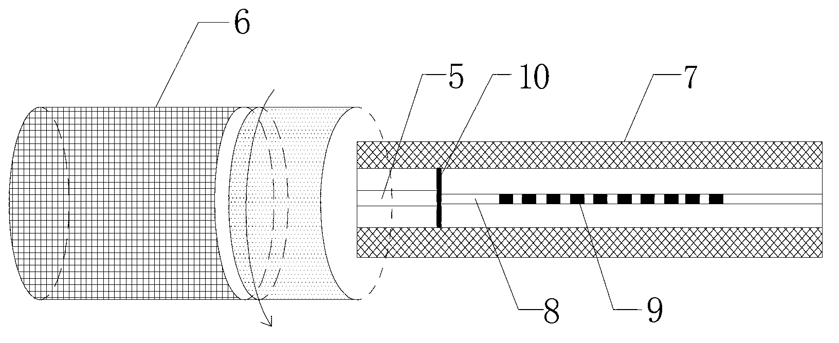
[0047] The sensing probe includes a single-mode fiber 5, a fiber twister 6 and a polarization-maintaining fiber probe 7, and the polarization-maintaining fiber probe 7 includes a polarization-maintaining fiber 8 and a polarization-maintaining fiber grating 9 written in the polarization-maintaining fiber 8, The single-mode fiber 5 and the polarization-maintain...

Embodiment 2

[0058] The torsional sensing device of this embodiment includes a VCSEL light source 1, a polarization processing unit, a sensing probe, an orthogonal polarization demodulation processing unit, and an optical fiber circulator 2, and the polarization processing unit, the sensing probe, and an orthogonal polarization demodulation processing The units are connected through a fiber optic circulator 2. The distance between the fiber twister 6 and the single-mode-polarization-maintaining fiber fusion splicing point 10 is 2mm. The rest of the structure and detection method are the same as in Example 1.


PUM

PropertyMeasurementUnit
Lengthaaaaaaaaaa
Lengthaaaaaaaaaa

Abstract

The invention discloses an orthogonal polarization fiber bragg grating vector torsion sensing device and a detection method thereof. The torsion sensing device comprises a vertical cavity surface emitting laser (VCSEL) light source, a polarization processing unit, a sensing probe, a orthogonal polarization demodulation processing unit and an optical fiber circulator/coupler, and the polarization processing unit, the sensing probe and the orthogonal polarization demodulation processing unit are connected through the optical fiber circulator/coupler. The detection method of the torsion sensing device includes that a polarization maintaining optical fiber bragg grating is used as a sensing unit, two groups of mutually orthogonal polarization state energy intensity messages are simultaneously obtained through an orthogonal polarization vector demodulation unit, and accurate measurement of torsion angles and directions can be achieved through a vector analysis module. The torsion sensing device uses a full optical fiber structure so that the torsion sensing device has the advantages of being high in integration level, good in stability, compact in structure, high in sensitivity, low in costs, easy to network and capable of achieving functions of temperature changing self-calibration and light source shaking inhibiting.

Description


Claims


Application Information

Patent Timeline
Owner JINAN UNIVERSITY
Why Eureka
Try Eureka