3D (three-dimensional) light field camera and method for processing images shot by same

A technology of a light field camera and a processing method, applied in the field of photography, can solve problems such as inability to display the screen correctly, and achieve the effects of high image resolution and simple device structure

Active Publication Date: 2013-04-03
TCL CORPORATION
View PDF5 Cites 16 Cited by
  • Summary
  • Abstract
  • Description
  • Claims
  • Application Information

AI Technical Summary

Problems solved by technology

[0004] The purpose of the present invention is to provide a 3D light field camera and its image processing method, which aims to solve the problem of depth inversion existing in the existing light field camera when recording a three-dimensional scene, and the inability to correctly display the screen when reproducing

Method used


Image

  • 3D (three-dimensional) light field camera and method for processing images shot by same
  • 3D (three-dimensional) light field camera and method for processing images shot by same
  • 3D (three-dimensional) light field camera and method for processing images shot by same

Examples


no. 1 example

[0028] The implementation of the present invention will be described in detail below by taking a 3D light field camera as an example.

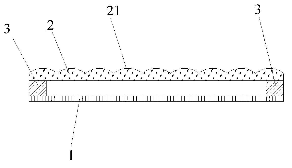
[0029] Please refer to attached figure 1 , a 3D light field camera, comprising a CCD image sensor 1 and a lenticular lens array 2 arranged parallel to each other, the lenticular lens array 2 is composed of several lenticular lenses 21 arranged side by side, the CCD image sensor 1 and the lenticular lens The distance between the arrays 2 is equal to the focal length of the lenticular lenses 21 . Wherein, the CCD image sensor 1 is used to record image information, which is covered with CCD pixels; the cylindrical lens array 2 is used to separate and focus the externally incident light on the CCD image sensor and form interpenetrating Arranged multiple parallax maps, because the distance between the CCD image sensor 1 and the lenticular lens array 2 is equal to the focal length of the lenticular lens, the lenticular lens array 2 can make multipl...

no. 2 example

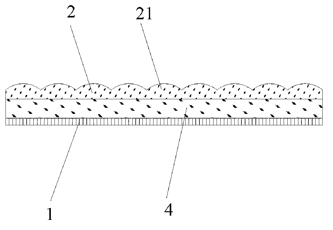
[0032] like figure 2 As shown, the difference between this embodiment and the first embodiment is that a light-transmitting substrate 4 is used between the CCD image sensor 1 and the lenticular lens array 2 to replace the gasket 3 in the first embodiment. The thickness of the transparent substrate 4 is equal to the focal length of the lenticular lens 21 . In this way, external light can be imaged on the CCD image sensor after passing through the lenticular lens array to form a plurality of parallax maps interspersed with each other.

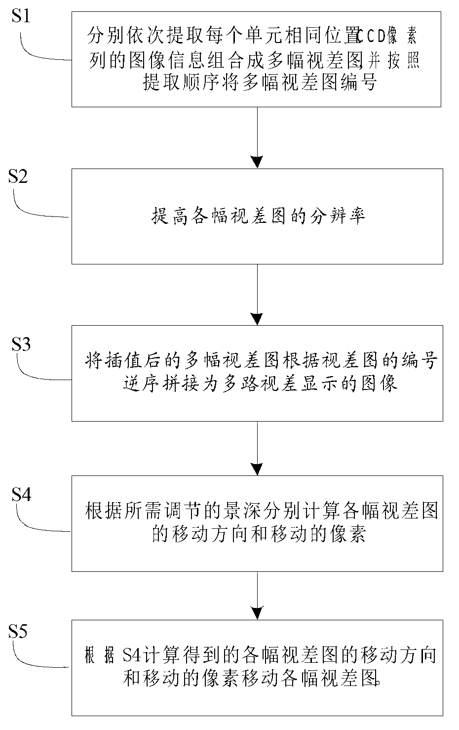
[0033] The present invention also provides a method for processing images captured by a 3D light field camera as in Embodiment 1 or Embodiment 2, comprising the following steps:

[0034] S1 sequentially extracts the image information of the CCD pixel column at the same position of each unit and combines them into multiple disparity maps, and numbers the multiple disparity maps according to the order of extraction;

[0035] Please refer to atta...


PUM


Abstract

The invention belongs to the field of display technology, and relates to a 3D (three-dimensional) light field camera and a method for processing images shot by the same. The 3D light field camera comprises a CCD (charge coupled device) image sensor and a cylindrical lens array used for separating light rays transmitted into the 3D light field camera from the external and focusing the light rays on the CCD image sensor. The CCD image sensor and the cylindrical lens array are parallel to each other, the cylindrical lens array comprises a plurality of cylindrical lenses which are arranged side by side, and the distance from the CCD image sensor to the cylindrical lens array is equal to the focal distance of the cylindrical lens array. The cylindrical lens array is placed in front of the CCD image sensor, so that the light field camera can extract a plurality of disparity maps, and by the method for increasing resolution ratios of the disparity maps, arranging the disparity maps in an inverse order and shifting the disparity maps, animation-out and animation-in effects are realized for a three-dimensional scene. The 3D light field camera and the method have the advantages that equipment is simple in structure, the acquired images are high in resolution ratio, and the technical animation-out and animation-in effects are realized.

Description

technical field [0001] The invention belongs to the technical field of imaging, and in particular relates to a 3D light field camera and a method for processing images captured by it. Background technique [0002] Light field cameras originate from integrated imaging technology, which was first proposed by Lippmann and is a display technology that uses lens arrays to record and reproduce 3D scenes. Light field cameras generally place a lens array in front of the CCD image sensor, and record information in different directions of the three-dimensional scene on the focal plane through the lens array. There are two purposes of the light field camera: first, it can meet the needs of shooting first and then focus, that is, it does not need to focus when shooting; second, it can record the information of the three-dimensional scene. [0003] When a light field camera based on a lens array is used to capture a three-dimensional scene, the image resolution is greatly reduced, becau...

Claims


Application Information

Patent Timeline
IPC IPC(8): G03B35/08H04N5/232
Inventor 濮怡莹谢相伟
Owner TCL CORPORATION
Why Eureka
Try Eureka