Automatic change-over switching device

A technology of automatic transfer switch and micro switch, which is applied in the direction of electric switches, circuits, electrical components, etc., can solve problems such as wrong opening and closing operations, production, life impact, and cumulative errors, so as to avoid misoperation problems and reduce transmission. Series, the effect of reducing the cumulative error

Active Publication Date: 2013-04-03
SCHNEIDER WINGOAL TIANJIN ELECTRIC EQUIP
View PDF4 Cites 3 Cited by
  • Summary
  • Abstract
  • Description
  • Claims
  • Application Information

AI Technical Summary

Problems solved by technology

But there is following problem in this automatic transfer switch electrical appliance of this prior art: only be provided with motor support on this automatic transfer switch electrical appliance, motor 2 controls breaker 3 opening and closing by escapement 4, but, as mentioned above, motor 2 is installed on the motor bracket, the escapement 4 is installed on the mandrel 8, and the circuit breaker 3 is installed on the bottom plate 1. Since these transmission parts are installed on different parts, it may be caused by multi-stage The accumulative error in the position of the escapement 4 caused by transmission caused it to mistakenly touch the micro switch installed on the circuit breaker 3 to make it act. As a result, the micro switch sent an error signal to the controller, and finally the circuit breaker 3 Wrong opening and closing operations under the control of the controller will undoubtedly have a serious impact on normal production and life
In addition, the operation accuracy of the escapement 4 with this structure on the switch handle 7 is not good, so the safety is poor.

Method used


Image

  • Automatic change-over switching device
  • Automatic change-over switching device
  • Automatic change-over switching device

Examples


Embodiment Construction

[0018] The automatic transfer switch appliance provided by the present invention will be described in detail below in conjunction with the accompanying drawings and specific embodiments. The same symbols are used for the same components as those in the prior art, and their descriptions are omitted.

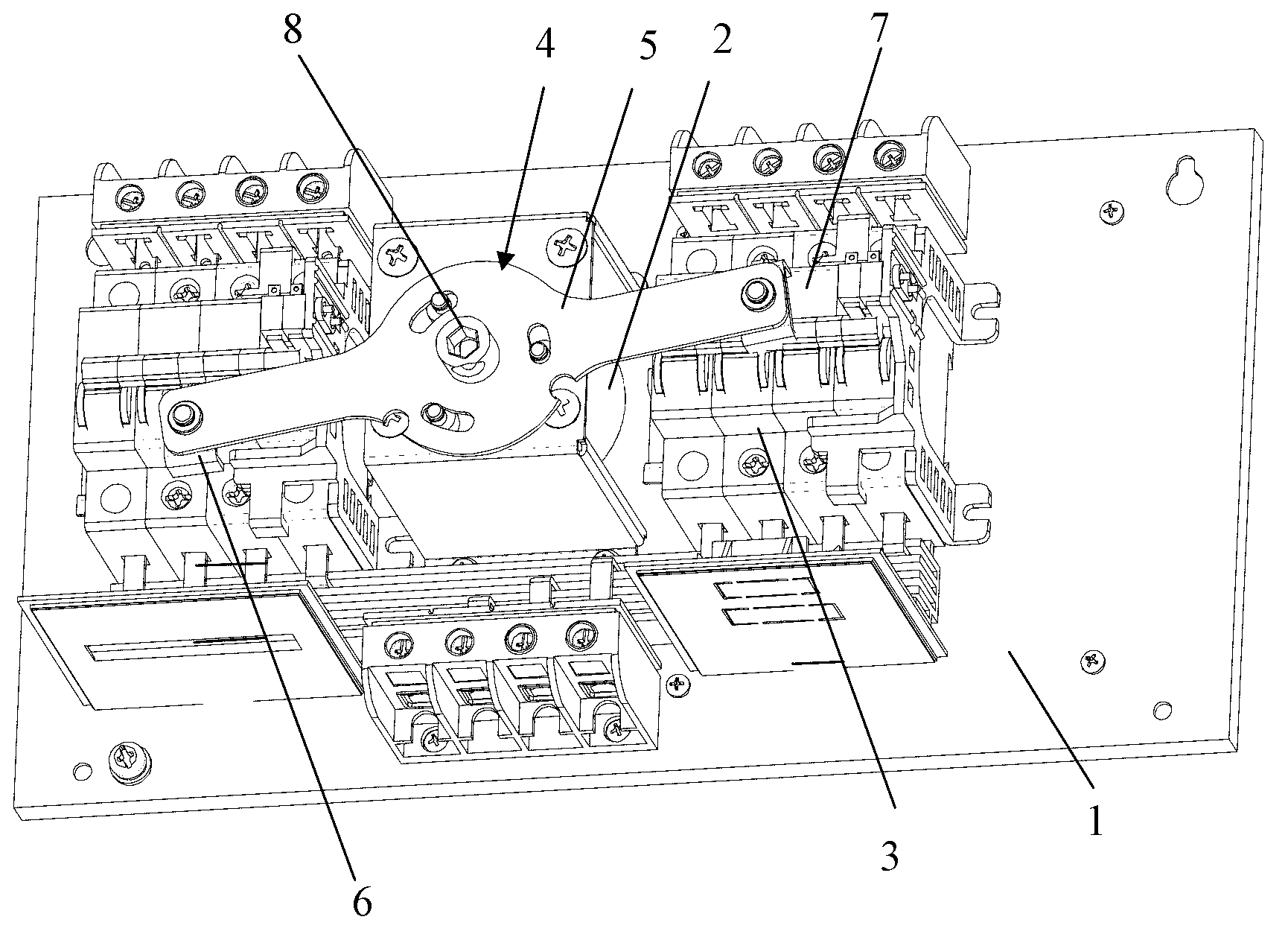
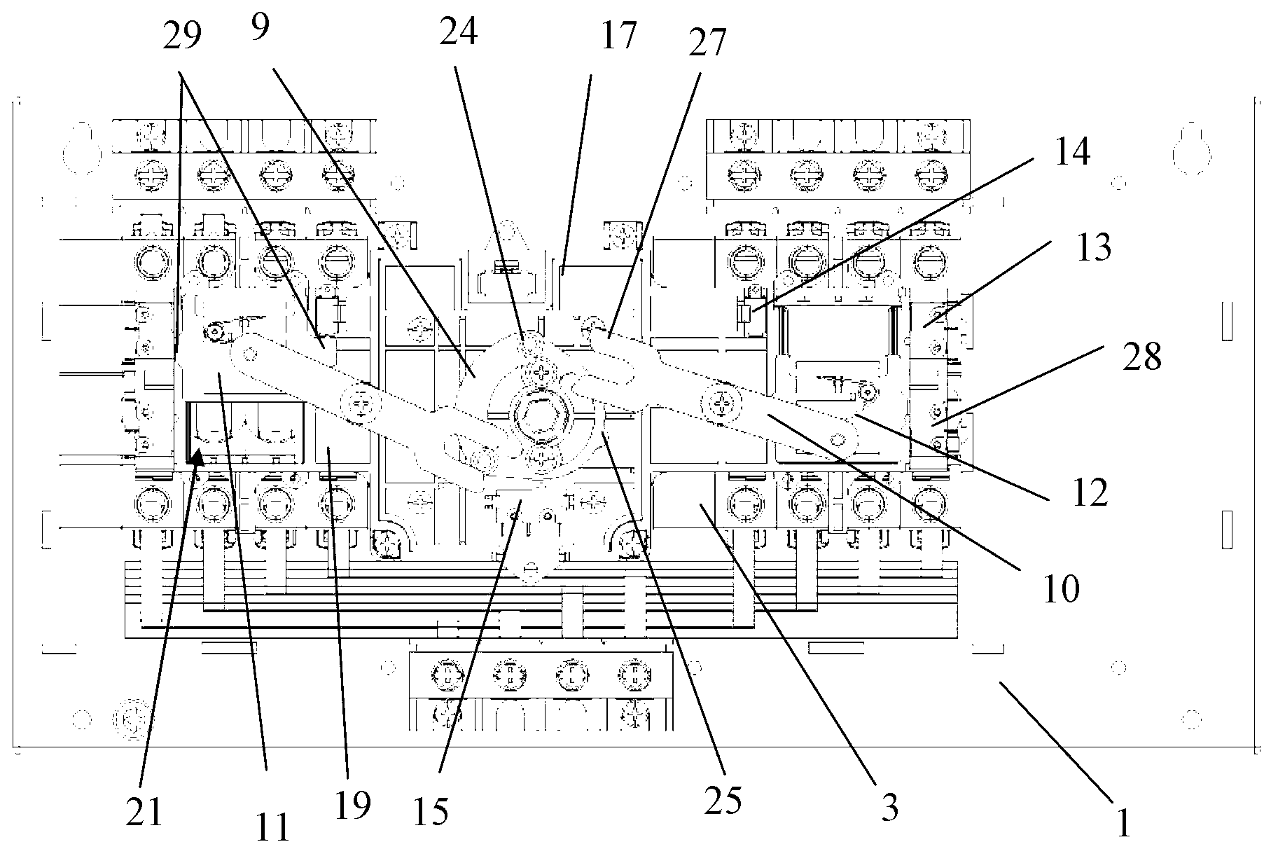
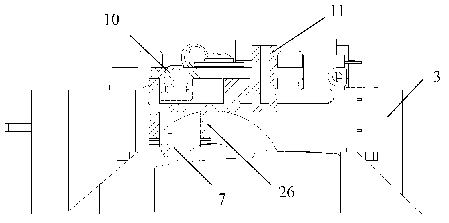
[0019] Such as Figure 2-Figure 7 and figure 1 As shown, the automatic transfer switch appliance provided by the present invention includes a base plate 1, a combined bracket, a motor 2, two circuit breakers 3, a mandrel 9, two escapements 10, two sliders 11, two leaf springs 12, two An indicator light microswitch 13, two motor stop microswitches 14, a double-point microswitch 15, controllers and shells not shown in the figure; The lower integral support 16 is composed of a fixing piece 17, wherein the lower integral support 16 is composed of a motor support 18 and two switch fixing frames 19 respectively located on both sides of the motor support 18. The middle part of the moto...


PUM


Abstract

An automatic change-over switching device comprises a base plate, a combined support, a motor, two circuit breakers, a mandrel, two release catches, two sliders, two plate springs, two indicator lamp microswitches, two motor stopping microswitches, a double-pole microswitch, a controller and a casing. The motor and the circuit breakers are all fixed on the combined support, so that transmission level of a transmission part can be effectively reduced, accumulated errors of the position of the transmission part caused by multi-level transmission during working can be reduced, the problem of misoperation caused accordingly can be solved, and normal production can be ensured. Further, a transmission operation mechanism on the automatic change-over switching device is reasonable in structure, and an operating member has accuracy in operating switch handles on the circuit breakers and is high in safety.

Description

technical field [0001] The invention belongs to the technical field of electrical equipment, in particular to an automatic transfer switch electrical appliance. Background technique [0002] The automatic transfer switch appliance is a widely used terminal appliance. It mainly uses the controller on it to drive the electric operating mechanism to control the action of the switch, so as to connect or break the common and standby power supply, so as to ensure the safety and production of the power system. continuity. figure 1 It is a schematic diagram of the main components of a commonly used automatic transfer switch appliance. Such as figure 1 As shown, this automatic transfer switch appliance mainly includes a base plate 1, a motor 2, two circuit breakers 3, a mandrel 8, an escapement 4, a controller and a casing not shown in the figure; wherein the motor 2 is installed on the The middle part of the surface of the base plate 1; two circuit breakers 3 are respectively arr...

Claims


Application Information

Patent Timeline
Patent Type & Authority Applications(China)
IPC IPC(8): H01H9/02H01H3/32
Inventor 陈红群岳鹏梁超周峰茌林涛午建伟刘淼
Owner SCHNEIDER WINGOAL TIANJIN ELECTRIC EQUIP
Why Eureka
Try Eureka