Wire clamping device with horn mouth

A technology of wire gripper and bell mouth, which is applied in the field of equipment, can solve the problems of low wire clamping force, influence of wiring speed, easy loosening, etc., and achieve the effect of stable contact, prolonging service life and firm combination

Active Publication Date: 2013-04-03
NINGBO CONNFLY ELECTRONIC CO LTD
View PDF6 Cites 7 Cited by
  • Summary
  • Abstract
  • Description
  • Claims
  • Application Information

AI Technical Summary

Problems solved by technology

Commonly used wire clamps in the market do not have a guide design, which has a greater impact on the wiring speed when a large number of wire clamps are docked; at the same time, the clamping force of the wire clamps on the wires is not high, and it is easy to loosen after a long period of use; ordinary wire clamps Mostly designed for constant current, easy to damage when encountering complex current

Method used


Image

  • Wire clamping device with horn mouth
  • Wire clamping device with horn mouth
  • Wire clamping device with horn mouth

Examples


Embodiment Construction

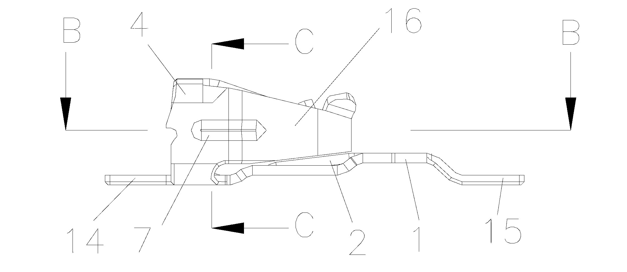
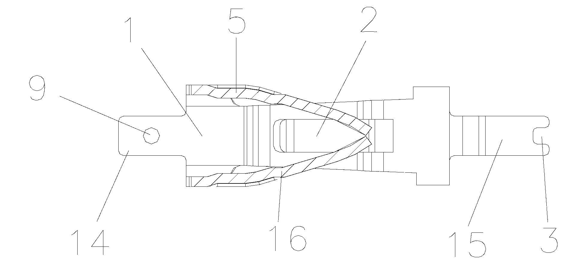
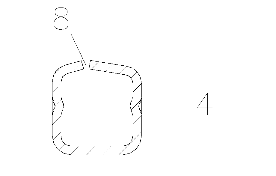
[0024] like Figure 1-12 As shown, a wire gripper with a bell mouth according to the embodiment of the present invention includes a fixed base 1 with an arched middle part, and is characterized in that: an elastic piece 2 is provided in the middle of the fixed base 1; 1 Both ends are respectively provided with a left welding piece 14 and a right welding piece 15, the left welding piece 14 is provided with a welding through hole 9, and the right welding piece 15 is provided with a welding groove 3; the left end of the fixed base 1 A conduction ring 4 is provided, and the two sides of the conduction ring 4 and the top of the conduction ring 4 are respectively provided with a left blade 5, a right blade 16 and a top blade 6, and the left blade 5, the right blade 16 and the top blade The blades 6 are bell-shaped, and the connecting parts of the left blade 5 and the right blade 16 and the conduction ring 4 are provided with reinforcing ribs 7 . The left blade 5, the right blade 16...


PUM


Abstract

The invention relates to a wire clamping device with a horn mouth. The wire clamping device comprises a fixed base, the middle of the fixed base is arched upwards, an elastic piece is arranged in the middle of the fixed base, a left welding piece and a right welding piece are arranged at two ends of the fixed base, a welding through hole and a welding groove are respectively arranged on each welding piece, a conduction ring is arranged at the left end of the fixed base, a left vane and a right vane are arranged on two sides of the conduction ring respectively, a top vane is arranged at the top end of the conduction ring, and reinforcing ribs are arranged at connection positions of the side vanes and the conduction ring. The wire clamping device has the advantages that the welding area is enlarged through the welding through holes and the welding grooves, so that the wire clamping device and a printed circuit board are more firmly combined, the contact area of the wire clamping device and a wire is enlarged by the top vane and the elastic piece, so that the wire clamping device more stably contacts with the wire after the wire is clamped, and the clamping force of the wire clamping device and elasticity of the side vanes are enlarged by the reinforcing ribs, so that the service life of the wire clamping device is prolonged.

Description

technical field [0001] The invention relates to the field of equipment such as electronics, electric appliances and industrial automation. Background technique [0002] The cable clamp is an accessory product used to realize the connection of electronics, electrical appliances and industrial automation equipment. The connection method can be the connection inside the device itself or the connection between devices. It appears in the form of a device Electronics, electrical appliances, and various industrial automation control panels are often used to transmit current or signals to achieve docking between various devices. The docking process must ensure fast, efficient, very good stability and high engagement force between wires . Commonly used wire clamps in the market do not have a guide design, which has a greater impact on the wiring speed when a large number of wire clamps are docked; at the same time, the clamping force of the wire clamps on the wires is not high, and ...

Claims


Application Information

Patent Timeline
Patent Type & Authority Applications(China)
IPC IPC(8): H01R12/75H01R12/57H01R13/24H01R13/193
Inventor 丁青松
Owner NINGBO CONNFLY ELECTRONIC CO LTD
Why Eureka
Try Eureka